
Getting Started with Digital I/O on Arduino
Arduino boards are incredibly popular microcontrollers. The tiny yet mighty devices are versatile, handling basic projects such as blinking LEDs and controlling servo motors to advanced uses such as robotics or smart home automation with equal grace. Learn about getting started with digital I/O (input/output) on the Arduino!
What is An Arduino?
An Arduino is a microcontroller. While there are tons of different Arduino models, from the Arduino UNO to the Arduino Nano and even unofficial Arduino clones, the basic premise is the same. The board connects to various hardware components such as breadboards, LEDs, servo motors, sensors, and a whole host of different devices. Then, code is written and uploaded to an Arduino board via the Integrated Development Environment (IDE). So to use an Arduino, you'll need both the hardware components such as an Arduino board and accessories such as stepper motors as well as an Arduino IDE and compatible code. Then, when uploaded and executed, Arduino code powers on and off hardware connectors to bring about a desired effect like blinking an LED at a certain time interval or rotating a servo to a specific angle.
What are Arduino Digital I/O Pins?
 1sfoerster / CC BY-SA (https://creativecommons.org/licenses/by-sa/3.0)
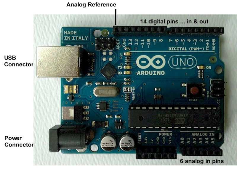
Before you can actually use Arduino digital I/O pins, you'll first need to understand what they actually are. As the name suggests, I/O pins on an Arduino are special in that they may be employed as inputs or outputs. In turn, these input/output digital Arduino pins let you connect sensors and various integrated circuits. Once connected properly, digital Arduino I/O pins allow you to read light indicators or switch inputs.
Analog signal inputs on an Arduino can assume a range of different values. But digital I/O signals are limited to two states, low (0), and high (1). As such, you can use digital and analog pins in conjunction, such as powering on and off an LED light.
How to Use Digital Inputs and Outputs on the Arduino
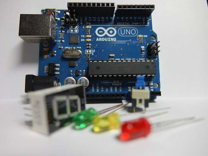
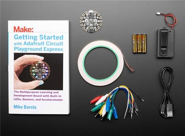
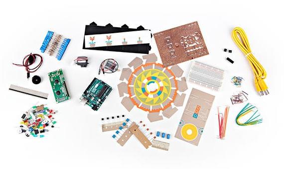
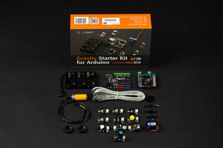
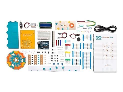
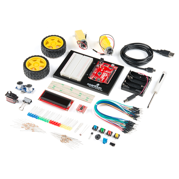
There are almost limitless ways to take advantage of digital inputs and outputs on Arduino microcontrollers. A great example is using push buttons for powering on and off LEDs. With a push button and LED connected, you'll be able to press the button to toggle the LED on and off. The specific way you connect everything might vary somewhat depending on what Arduino board you're using, but the general premise should be the same. I used an Arduino Uno R3, as well as a couple basic components including an 830 tie-point breadboard, red LED, 220 Ohm resistor, several male-male jumper wires, and a pair of push button switches. You can buy all parts individually, or pick up an Arduino starter kit.
Parts list:
- Arduino Uno R3 (or another Arduino MCU)
- Breadboard
- 5mm LED
- 220 Ohm resistor
- 7 x male-male jumper wires
- 2 x push button switches
My wiring was such, but yours might vary:
- Jumper cable - Arduino Uno R3 Digital pin 5>Breadboard G27
- Jumper cable - Arduino Uno R3 digital pin 8>Breadboard D32
- Jumper cable - Arduino Uno R3 digital pin 9>Breadboard D28
- Jumper cable - Arduino Uno R3 didigal pin GND>Breadboard power rail
- Jumper cable - Breadboard power rail>Breadboard H22
- LED - Breadboard I22>Breadboard I23
- Push button - Breadboard F28, F30, E28, E30
- Push button - Breadboard F32, F34, E32, E34
- Resistor - Breadboard H23>Breadbaord H27
Now, for the code. In your Arduino IDE (integrated development environment), enter the following code:
int ledPin = 5;
int buttonApin = 9;
int buttonBpin = 8;

byte leds = 0;

void setup()
{
  pinMode(ledPin, OUTPUT);
  pinMode(buttonApin, INPUT_PULLUP);
  pinMode(buttonBpin, INPUT_PULLUP);
}

void loop()
{
  if (digitalRead(buttonApin) == LOW)
  {
    digitalWrite(ledPin, HIGH);
  }
  if (digitalRead(buttonBpin) == LOW)
  {
    digitalWrite(ledPin, LOW);
  }
}
Let's break down what's going on here. The lines pinMode(buttonApin, INPUT_PULLUP); and pinMode(buttonBpin, INPUT_PULLUP); dictate the pinMode being used. Since INPUT_PULLUP is specified, that means the pin is being utilized as an input rather than an output. The first three lines show the variables for the pins being used with ledPin as an output pin, while buttonApin refers to the switch closest to the top of the breadboard, and buttonBpin is the bottom-most push button. ledPin is a standard OUTPUT.
How to Use Digital I/O Pins on the Arduino - Arduino Digital Pins Explained
Digital inputs and outputs on Arduino MCUs are incredibly handy. Because I/O pins may be used as either inputs or outputs, they're versatile and rely on code uploaded to the Arduino IDE to specify whether it's being employed as an input or output. You can take advantage of digital I/O pins in conjunction with other components. For example, you can use push buttons to toggle on and off an LED. Or, you may blink an LED with a delay using jumper cables, a resistor, and LED. There are loads of different applications in which digital input/output Arduino connectors may benefit your maker projects.
Your turn: How are YOU using digital I/O pins in your DIYing?

Moe Long is an editor, writer, and tech buff with a particular appreciation for Linux, Raspberry Pis, and retro gaming. Writing online since 2013, Moe has bylines at MakeUseOf, TechBeacon, DZone, SmartHomeBeginner, DEV.to, DVD Netflix, and Electropages. You can read his writings on film and pop culture at Cup of Moe, check out his tech reviews, guides, and tutorials at Tech Up Your Life, and hear his thoughts on movies on the Celluloid Fiends podcast. Aside from writing and editing, Moe has an online course, the Beginner's Guide to Affiliate Blogging From Scratch. When he's not hammering away at his keyboard, he enjoys running, reading, watching cinema, listening to vinyl, and playing with his dog Sebastian.


Leave your feedback...