
Z80 Computer Project - Programming EEPROM Memory
Earlier, we learned how to add memory to our Z80 system, and how the memory decoder separates ROM from RAM. But now we need to learn how to get programs onto our computer by building an EEPROM programmer!
Memory Recap
In the previous project article, we learned about how memory works, and its role in our Z80 computer project. Before we jump into physically building the computer, as well as construct a memory programmer, we will first quickly go over key details from the previous articles to refresh our memory (pun intended).
Memory is the area that stores information for our computer to use when needed. Memory can be used to hold instructions as well as data including variables, images, IDs, etc. Memory itself often comes in two main forms; Read-Only Memory (ROM), and Random-Access Memory (RAM). ROM is generally used to hold programs (such as the Basic Input Output System, or BIOS), while RAM is used to hold applications, data, and variables. In our Z80 computer, the ROM will hold the program, while RAM will hold variables for the program such as counters, timer values, and results of equations.
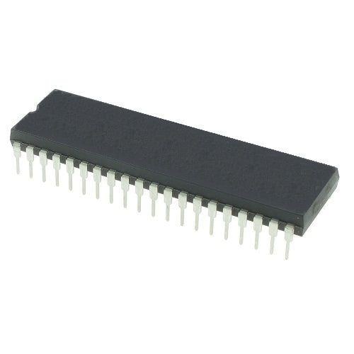
In this project, we will need to write programs for the Z80 that will get stored in ROM, but we need to learn how to get these programs into the ROM chip for the computer to read. The specific memory chip that we will be using in this project is an AT28C256 Electrically Erasable Programmable Read Only Memory (EEPROM) that holds 32KB of data. This chip, once programmed, will remember the data even when the power is turned off, which is why we will be using it.
EEPROM Write Cycle
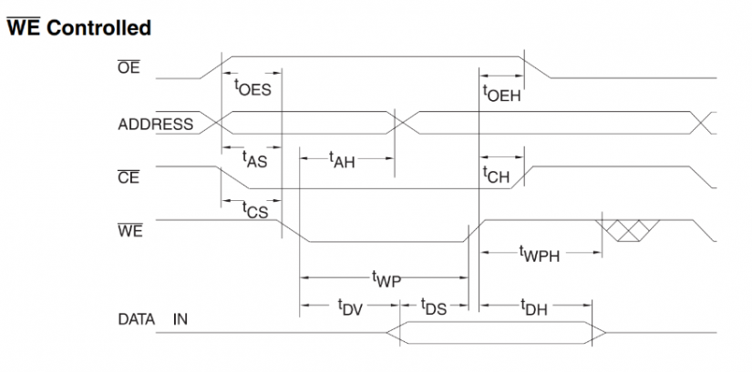
Since we will be learning how to put data into the EEPROM chip from a computer so we can program our Z80 computer we first need to learn how the write cycle works for an EEPROM devices. The chip is controlled with three pins; WR, OE, and CS. WR is the write pin, and this is used to save data into the chip. The OE pin is used to read data from the chip, and the CS pin is used to select the memory chip itself. Both read and write cycles need the CS to be used otherwise the chip won’t know it is in use.
Write cycles are very simple and use the following logic:
- Make sure CS, WR, and OE are all a logical 1 (these are active low pins)
- Set the address pins to the memory address you want to save to
- Set the data pins to the data that you want to store
- Set CS to 0
- Set WR to 0. This is where the data is latched in
- Set WR to 1
- Set CS to 1. You are now all done!
The memory chip takes a while to save the data (up to 10ms), so its important that you leave a few ms pause between each step.
http://ww1.microchip.com/downloads/en/DeviceDoc/doc0006.pdf
DIY Programmer - Hardware
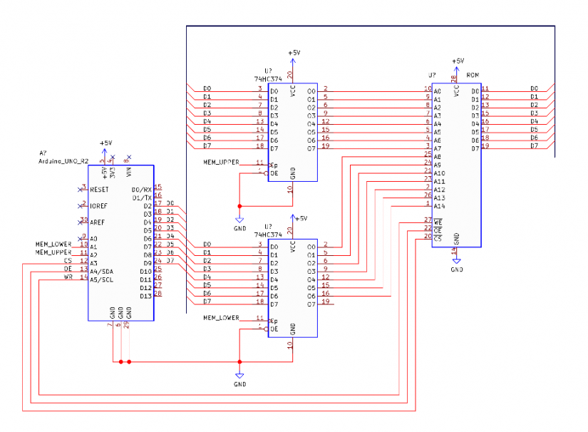
So, now that we know how to save data to the EEPROM its time to build our programmer. Unfortunately, we have to build a programmer that sits separate from the Z80 as the memory IC cannot be programmed while in the computer. This means that whenever we want to change the program, we have to physically remote the IC from the computer, and place it into the programmer. To keep things simple, we will have the programmer on the same breadboard as the computer.
The programmer is based on an Arduino Uno as this is a very easy device to create prototype designs on. However, those who are smart will quickly realise that we only have 12 digital I/O on the Uno (0 and 1 are used for TX, RX), and 6 analogue inputs, but the EEPROM has 15 address inputs, 8 digital IO, and 3 control pins. This means we are 26 – 18 = 8 pins short. Now, we could use less address pins on the memory chip, but this would result in only have a 256-byte space to put programs in. In order to expand our I/O, we will instead incorporate two 74HC374 latches. Each one of these latches can hold 8-bits of data, and if all are connected to a common bus, then we can have up to 24-bits from only a single 8-bit output and 3-bit control from the Uno. The reason why we do not need a third latch for the data bus is because we can connect the data bus of the memory IC directly to the common bus; the chip will only save data when the WR pin goes low!
DIY Programmer – Software
The EEPROM programmer is only 30% hardware as it’s the software that makes this project possible. Our software needs to be able to run the Uno to correctly save bytes into the EEPROM, while also correctly reading data from a program that runs on our computer. To keep the project cross-platform, we will be using Python as the scripting language for the PC application.
When our PC tells the programmer to save data over a serial connection, we need to ensure that the data sent is not corrupted. Instead of sending data as raw bytes (which is fast), we will instead use a near-identical method to our Custom IoT Series that utilizes text-based messaging. The advantage of this is that data is sent in its ASCII format, and thus is easily distinguishable in messages. This also allows us to reserve special byte characters for commands such as save data, load data, and reset messages. All data sent from the PC will be in the form of hex consisting of two characters per byte. For example, if we want to send the byte 0xFF, we instead send the ASCII characters FF. Other characters of the alphabet will be reserved for special commands as shown in the table below.
PC to Uno Messages
| Character | Command |
| R | Reset system |
| S | Save byte message |
| P | Save page message |
| G | Get byte message |
| H | Set higher byte of address |
| L | Set lower byte of address |
Uno to PC Messages
| Character | Command |
| Y | Command was good (Y) |
| N | Command not understood (N) |
Uno Software
The software for the Uno mostly uses standard Arduino libraries with the exception of the 8-bit port library. One of the issues faced with the Arduino Uno is that communicating to an 8-bit bus is difficult without using the AVR registers. However, there is a library, called 8-Bit IO Port, that allows us to combine any 8 pins on the Arduino to create a port that can be communicated to.
The function of the software on the Uno is very straight forward; wait for a command through the serial port, decode the message, execute the command, and then send the appropriate response back. While we could have used the Serial.readline() instruction to keep things simple, it resulted in a very slow piece of software. Thus, our software utilises a custom read function that takes in individual characters, puts them into a buffer, and then checks for a terminating character. From there, the buffer is then transferred into a string, which is then checked for command characters.
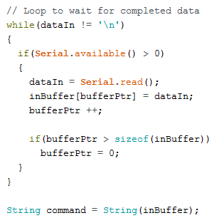
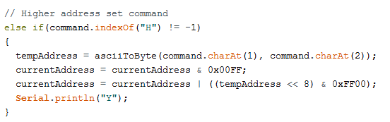
Custom read function (left), and command decoding (right)
Python Script
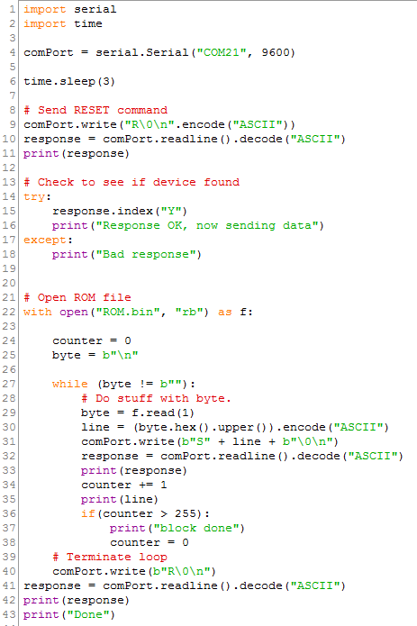
The Python script is incredibly basic; it loads a file called ROM.bin in the same directory as the python file, resets the Uno, and then streams each byte to the memory chip. Each command sent to the Uno is terminated with a zero character as well as a new line (\0 \n), to ensure that the Uno correctly terminates the custom read command while loop.
Z80 Assembly Language
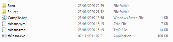
Programming the Z80 requires a program called an assembler; this program takes in CPU instructions and turns them into bytes that the CPU can actually read. While there are many assemblers to choose from, my personal experience is that tnyASM is by far the best. However, this program is a console application making it somewhat tricky to use. But never fear, for I is here, and included in these project files is not only the assembler, but a custom Compile.bat file that will launch the compiler, and pass the correct parameters to compile your program. The program will compile the file in the src directory called main.asm, so make sure your code is in that file! Once compiled, your ROM.bin file will be located in the Rom directory, and this is what you place in the same directory as the python script.
Unfortunately, describing how the Z80 assembly language works is far too complex, and is a whole project series in its own right. However, you will be lucky to know that there are a ton of resources online that you can learn from that include example projects!
Bootloader.py:
import serial
import time

comPort = serial.Serial("COM21", 9600)

time.sleep(3)

# Send RESET command
comPort.write("R\0\n".encode("ASCII"))
response = comPort.readline().decode("ASCII")
print(response)

# Check to see if device found
try:
    response.index("Y")
    print("Response OK, now sending data")
except:
    print("Bad response")


# Open ROM file
with open("ROM.bin", "rb") as f:

    counter = 0
    byte = b"\n"

    while (byte != b""):
        # Do stuff with byte.
        byte = f.read(1)
        line = (byte.hex().upper()).encode("ASCII")
        comPort.write(b"S" + line + b"\0\n")
        response = comPort.readline().decode("ASCII")
        print(response)
        counter += 1
        print(line)
        if(counter > 255):
            print("block done")
            counter = 0
    # Terminate loop
    comPort.write(b"R\0\n")
response = comPort.readline().decode("ASCII")
print(response)
print("Done")
Programmer.ino:
#include "IO_Port_8bit.h"

IO_Port_8bit port(2, 3, 4, 5, 6, 7, 8, 9, 'I'); //create port object

#define   MEM_LW  A1
#define   MEM_UP  A2
#define   MEM_CS  A3
#define   MEM_RD  A4
#define   MEM_WR  A5

char inBuffer[32];
char bufferPtr;
char dataIn;

int currentAddress;
int tempAddress;
byte tempByte;

String byteToAscii(byte b);
byte asciiToByte(char upper, char lower);
void writeByte(int address, char data);
void saveByte(int address, byte data);
byte readByte(int address);


void setup() {

  pinMode(A1, OUTPUT);
  pinMode(A2, OUTPUT);
  pinMode(A3, OUTPUT);
  pinMode(A4, OUTPUT);
  pinMode(A5, OUTPUT);

  digitalWrite(MEM_LW, LOW);
  digitalWrite(MEM_UP, LOW);
  digitalWrite(MEM_CS, HIGH);
  digitalWrite(MEM_RD, HIGH);
  digitalWrite(MEM_WR, HIGH);

  Serial.begin(9600);

  // Disable write protect system
  saveByte(0x5555, 0xAA);
  saveByte(0x2AAA, 0x55);
  saveByte(0x5555, 0x80);
  saveByte(0x5555, 0xAA);
  saveByte(0x2AAA, 0x55);
  saveByte(0x5555, 0x20);

  bufferPtr = 0;
}


void loop() {

  char dataIn = 0x00;
  bufferPtr = 0;

  // Loop to wait for completed data
  while(dataIn != '\n')
  {
    if(Serial.available() > 0)
    {
      dataIn = Serial.read();
      inBuffer[bufferPtr] = dataIn;
      bufferPtr ++;

      if(bufferPtr > sizeof(inBuffer))
        bufferPtr = 0;
    }
  }

  String command = String(inBuffer);

  // Save byte message
  if(command.indexOf("S") != -1)
  {
    saveByte(currentAddress, asciiToByte(command.charAt(1), command.charAt(2)));
    currentAddress ++;
    Serial.println("Y");
  }

  // Reset command
  else if(command.indexOf("R") != -1)
  {
    currentAddress = 0;
    Serial.println("Y");
  }

  // Higher address set command
  else if(command.indexOf("H") != -1)
  {
    tempAddress = asciiToByte(command.charAt(1), command.charAt(2));
    currentAddress = currentAddress & 0x00FF;
    currentAddress = currentAddress | ((tempAddress << 8) & 0xFF00);
    Serial.println("Y");
  }

  // Lower address set command
  else if(command.indexOf("L") != -1)
  {
    tempAddress = asciiToByte(command.charAt(1), command.charAt(2));
    currentAddress = currentAddress & 0xFF00;
    currentAddress = currentAddress | ((tempAddress) & 0x00FF);
    Serial.println("Y");
  }

  // Get byte message
  else if(command.indexOf("G") != -1)
  {
    Serial.println(byteToAscii(readByte(currentAddress)));
    currentAddress ++;
    Serial.println("Y");
  }
}


byte readByte(int address)
{
  // Set address
  byte lowerAddress = address & 0x00FF;
  byte upperAddress = ((address >> 8)& 0x00FF);
  byte dataIn = 0;
  port.set_IO_direction('O');

  // Latch the address to the two latches
  port.send_8bit_data(lowerAddress);
  delay(1);
  digitalWrite(MEM_LW, HIGH);
  delay(1);
  digitalWrite(MEM_LW, LOW);
  delay(1);
  port.send_8bit_data(upperAddress);
  delay(1);
  digitalWrite(MEM_UP, HIGH);
  delay(1);
  digitalWrite(MEM_UP, LOW);
  delay(1);

  // Read the data from the memory chip
  port.set_IO_direction('I');
  digitalWrite(MEM_WR, HIGH);
  digitalWrite(MEM_CS, LOW);
  digitalWrite(MEM_RD, LOW);
  delay(1);
  dataIn = port.get_8bit_data();
  delay(1);
  digitalWrite(MEM_RD, HIGH);
  digitalWrite(MEM_CS, HIGH);
  delay(1);

  return dataIn;
}


void saveByte(int address, byte data)
{
  // Set address
  byte lowerAddress = address & 0x00FF;
  byte upperAddress = ((address >> 8)& 0x00FF);
  port.set_IO_direction('O');

  // Latch the address to the two latches
  port.send_8bit_data(lowerAddress);
  digitalWrite(MEM_RD, HIGH);
  digitalWrite(MEM_LW, HIGH);
  digitalWrite(MEM_LW, LOW);
  port.send_8bit_data(upperAddress);
  digitalWrite(MEM_UP, HIGH);
  delay(1);
  digitalWrite(MEM_UP, LOW);

  // Write the data to the memory chip
  port.send_8bit_data(data);
  digitalWrite(MEM_CS, LOW);
  digitalWrite(MEM_WR, LOW);
  digitalWrite(MEM_WR, HIGH);
  delay(1);
  digitalWrite(MEM_CS, HIGH);
  port.set_IO_direction('I');
}


String byteToAscii(byte b)
{
  char upperHex = (b & 0xF0) >> 4;
  char lowerHex = b & 0x0F;
  String r = "";

  upperHex += 0x30;
  if(upperHex > 0x39)
    upperHex += 0x07;

  lowerHex += 0x30;
  if(lowerHex > 0x39)
    lowerHex += 0x07;

  r.concat(upperHex);
  r.concat(lowerHex);

  return r;
}

byte asciiToByte(char upper, char lower)
{
  upper = upper - 0x30;
  if(upper > 0x09)
    upper -= 0x07;

  lower = lower - 0x30;
  if(lower > 0x09)
    lower -= 0x07;

  return ((upper << 4 ) & 0xF0) | (lower & 0x0F);
}
Compile.bat:
z80asm.exe
Source\MAIN.ASM
Rom\DOS.bin

Pause- https://www.youtube.com/watch?v=LpQCEwk2U9w
- https://www.chibiakumas.com/z80/
- https://riptutorial.com/assembly/example/16904/zilog-z80-registers
Z80 Project Series - Programming EEPROM Memory Final Thoughts
This programmer will let you create your own programs for the Z80 platform, and will be essential in the projects to follow as we will begin to access I/O. While you can buy a programmer, building one not only teaches you about multiple platforms, it also allows you to be independent of commercial equipment that may not always be around.

Robin Mitchell is an electronic engineer who has been involved in electronics since the age of 13. After completing a BEng at the University of Warwick, Robin moved into the field of online content creation developing articles, news pieces, and projects aimed at professionals and makers alike. Currently, Robin runs a small electronics business, MitchElectronics, which produces educational kits and resources.


Leave your feedback...