
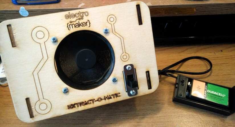
Build your own solder fume extractor
We love soldering. It is one of the most fundamental skills that any maker can learn, but the fumes produced by soldering aren’t good for you. However, before you start panicking, there are a few simple rules to follow.
- Always solder in well-ventilated area.
- If using lead solder ALWAYS wash your hands after soldering.
- Wear adequate eye protection; solder can spit
- Never leave a soldering iron unattended.
The first rule is ventilation, as we mentioned the fumes from soldering are a mix of flux and metals used to melt and make connections. So how can we protect our lungs from these nasty fumes? Well, a fume extractor is one way, and in this tutorial, we shall make our own using parts commonly found in our parts box/makerspace/garage.
For this project you will need
- A 60mm 12V PC fan
- 4 x 40mm M3 machine screws
- 2 x 10mm M3 machine screws
- 10 x M3 nuts
- A Switch
- DC Barrel Jack
- Length of speaker wire
- Heat shrink
- Soldering equipment
- 9 - 12 V DC power supply (check polarity, our supply was centre positive)
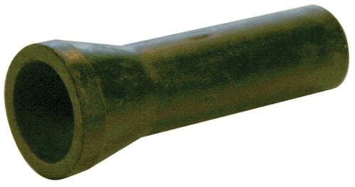
- Activated carbon foam filter
- Multimeter
- 9V PP3 battery
- PP3 connector to male barrel jack
For laser cutting
- 1 x A4 3mm laser grade plywood
- Laser cutter
Laser cutting the frame
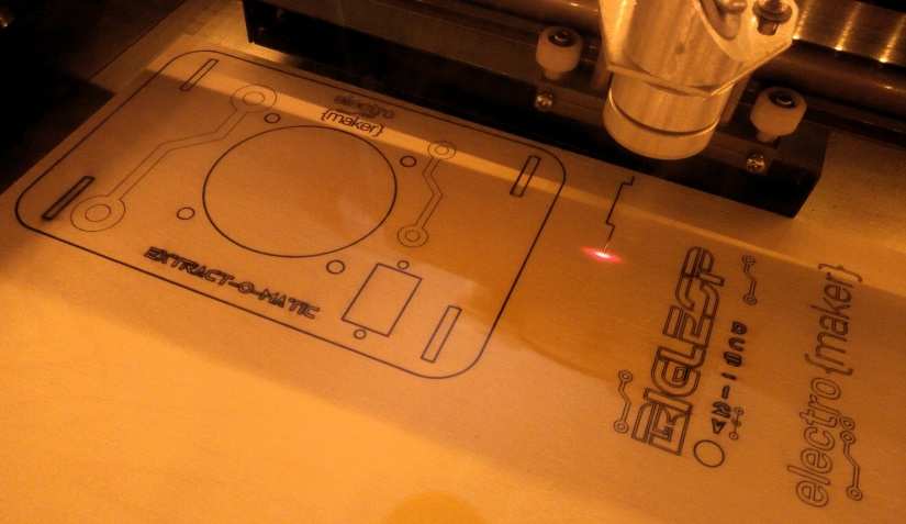
If you are not using a laser cut frame, you can skip this section. To laser cut the frame we used the K40 laser cutter that we have used in other projects. We have made an arcade cabinet and an MP3 ‘jukebox’ using our K40, and we have a guide to setting up your own K40 as part of the jukebox series.
Our frame is made from a single piece of A4 3mm thick plywood, which can be picked up from hardware stores. However, laser grade plywood is best sourced from reputable laser cutter material suppliers. Why is laser grade important? Well laser grade typically has fewer knots in the wood, and knots are not easy to cut, so the fewer we have, the better chance that our cut will work correctly.
To design our frame we shall use Inkscape, a free vector graphics editor, similar to Adobe Illustrator, which can be downloaded free from their website.
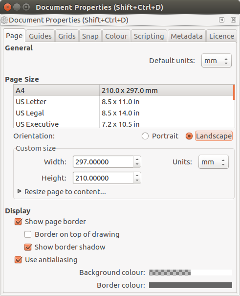
Using Inkscape we first set our document to use mm as the unit of measurement, this matches the units used by our laser cutter.
Click on File >> Document Properties and ensure that:
- Default units are mm
- Page Size is A4
- Orientation is Landscape
- Units are mm
Next, click on Grids and create a new rectangular grid which uses Grid units of mm.
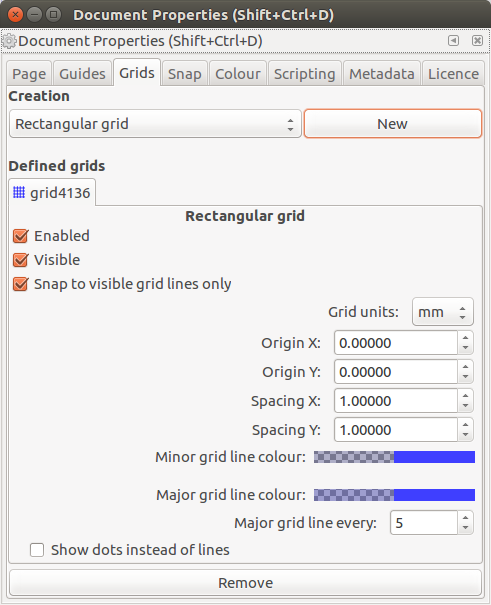
When complete, close the window and you will be returned to the document.
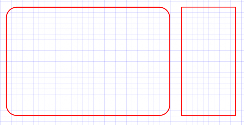
For our frame we decided to have a 150mm x 100mm rectangle with 20mm rounded corners. So using the rectangle tool from the tool menu on the left of the screen, draw a rough rectangle. Note that we are using the colour coding for our laser cutter software (K40 Whisperer) which means that:
Red = Vector Cut Blue = Vector Engrave Black = Raster Engrave
So pay careful attention as to what you would like to engrave or cut. Now click on the rectangle and then press Shift +ctrl+M to open the Transform dialog box. Click on Scale tab and change the width to 150.000 and the height to 100.000 mm. Then click on Apply.
Now that we have our perfectly sized rectangle, let’s add the 20mm rounded corners. For this we positioned the rectangle at 10mm on the x-axis (horizontal) and then zoomed in so that we could see the scale in 10mm increments. To zoom in press + and for zoom out press -. Once your zoom has been set, click on the rectangle tool and then click on the rectangle. You will see the top right point of the rectangle becomes a white circle. This indicates that we can use it to set the radius of the corner. So using left click and drag that circle until the radius is 20 mm, approximately two “boxes” in our grid.
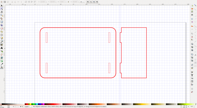
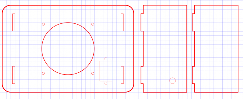
Next, we create a rectangle measuring 50mm by 100mm this will act as one of two ‘legs’ keeping the frame upright. Ensure that this is level with the original rectangle as we shall be transferring some measurements soon.
Our stands will friction fit (slot into holes) in the front panel and our wood is 3mm thick, so we need to create one 3mm wide by 20 mm tall slot using the rectangle tool. Remember to colour the stroke red to ensure it is a cut.
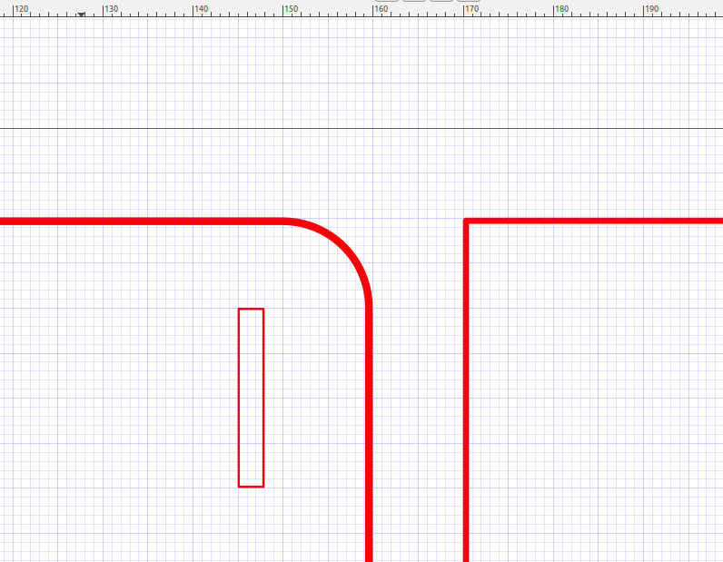
Our slot needs a tab which will slot neatly in place and we can do this really easily. Click on the slot and then go to Edit >> Duplicate and a copy of the slot will be created. Drag this slot over to the “leg” rectangle and place it slightly over the leg.
The tab is in place but it is not part of the rectangle, so select the ‘leg’ rectangle and the tab (SHIFT click) and from the Path menu select Union to join them.
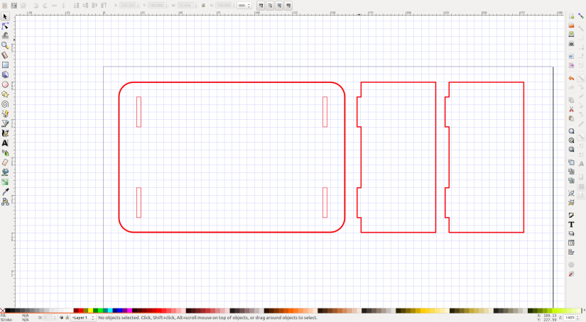
Now duplicate the same slot and use it to create another sot on the lower right section of the front panel.
Now create another tab on the rectangle to the right, just as we did earlier.
On the front panel duplicate the two slots and then move them to the left of the front panel, ensure they are placed at the same distance from the perimeter of the panel.
So now that we have slots cut, let’s cheat and duplicate the entire ‘leg’ rectangle.
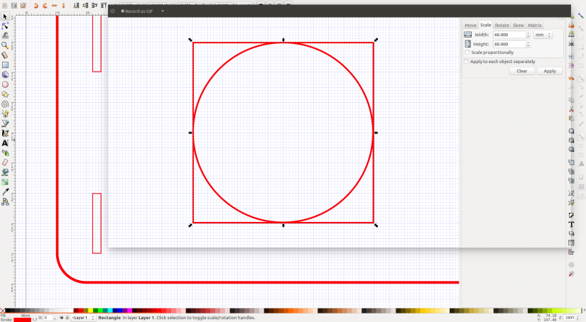
The basic pieces are made! But now we need to add a big hole for our fan to suck the fumes away. We know that our fan is 60mm in diameter, as that is what the box said. But for your fan, you will need to adjust the measurements. With that in mind we shall create a 60mm circle using the Circle tool but just as we did with the rectangle earlier, draw a rough circle and then press Shift+Ctrl+M to open the transform menu. Then scale the circle to 60mm (or whatever diameter your fan is) and click Apply.
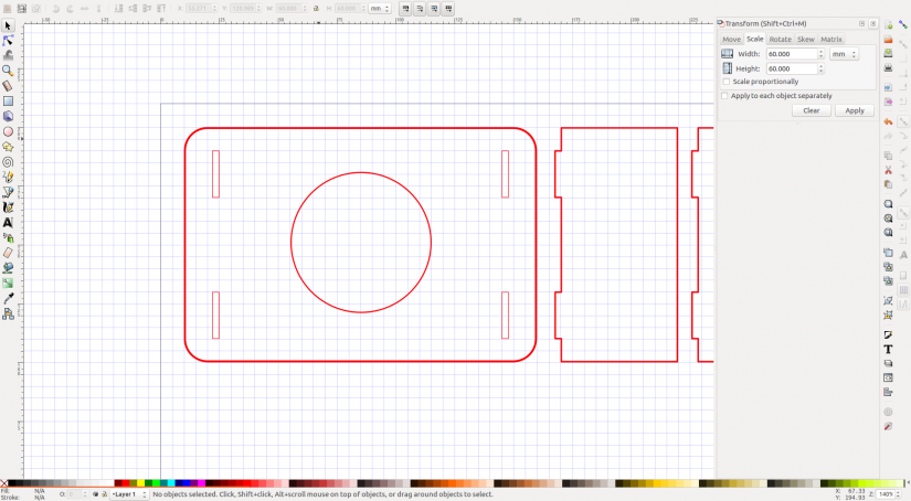
The hole for our fan needs to be placed centrally on the front panel (if you like symmetry) and the easiest way to do this is to select all the objects on the front panel, then deselect the fan hole(shift left mouse click). Next, go to Object >> Group and now our slots and front panel will be one object.
Highlight all of the front panel objects and then press Shift+Ctrl+A to open the Align and Distribute menu. From the Relative to: drop-down choose Selection Area (this will limit the alignment to just our front panel)
Now ungroup all of the objects in the front panel (we need to do this as the K40 software does not like grouped objects and it can produce some errors when cutting) by selecting all the front panel objects and then clicking on Object >> Ungroup.
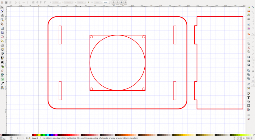
Our fan has a hole for the air to flow, but we need to secure it, and for that we need to create four additional circles, approximately 3mm in diameter and they need to be in corners of a square 60mm on each side. So draw a 60mm square and centre it over the circle.
Then draw a 3mm circle (remember to use the Transform menu Shift+Ctrl+M to set the size exactly.) and carefully place it in the top left corner of the square, zoom in and use Alt+Arrow Key to bump the 3mm circle into place. It should just be touching the inner red line of the square. Then duplicate the circle and place it in the top right, to the same spacing. Another opportunity to cheat now! Duplicate both the top left and right circles, and then move them both down to the bottom left and right respectively. You now have four 3mm circles around the main 60mm circle.
The 60mm guide square we created can now be deleted.
If you are adding a switch to your extractor, then a space will need cutting out of the front panel for its use. Our switch was 14mm wide by 23mm tall and along the centre line of the switch, spaced 1mm away from the top and bottom of the switch were two 3mm screw holes.
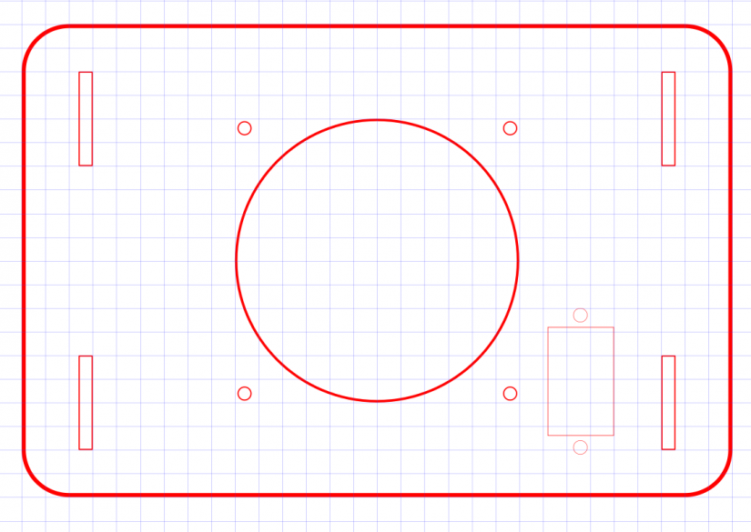
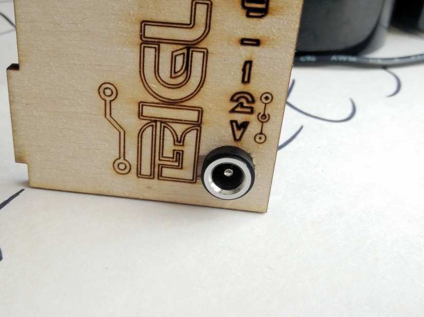
The last piece to this puzzle is a hole for our DC jack. Now placement of this hole is up to you. We chose the back right ‘leg’ as it made sense to tuck it away. The hole should match the diameter of the DC barrel jack being used, in our case it was 7mm.
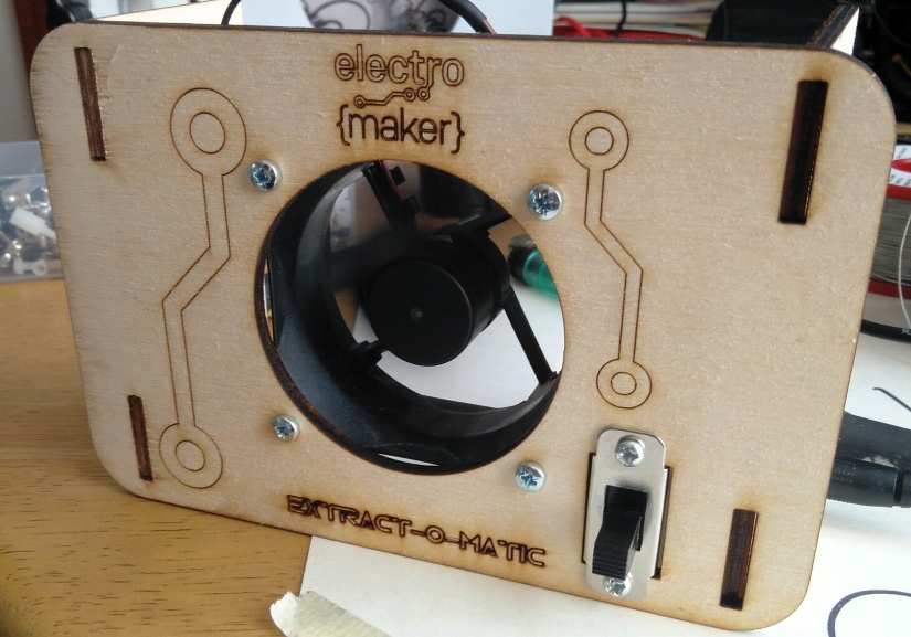
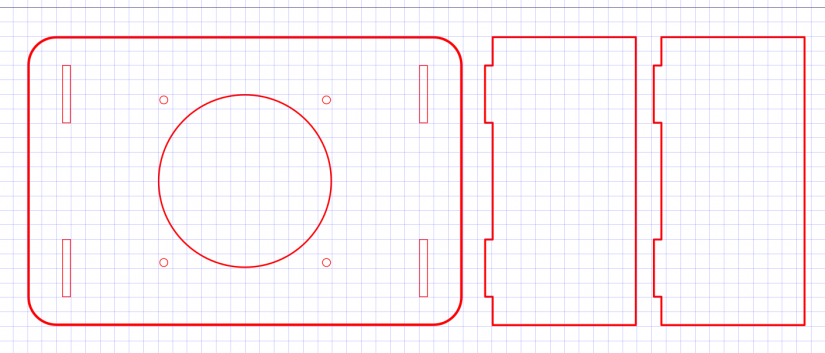
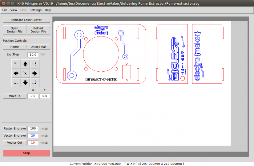
With the pieces created, we can now move over to the K40 laser cutter (or your model) and cut ourselves this frame. For our final piece, we added a few ‘understated embellishments’ to the design. Note that the blue lines refer to vector engraves, which draw the shapes on the wood as if we were using a pen and not a 40W laser!
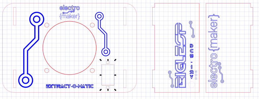
We’re using the K40 Whisperer software from Scorchworks, we’ve covered how to use this free software in a previous series, so go and take a look and take it for a test drive!
Soldering the circuit
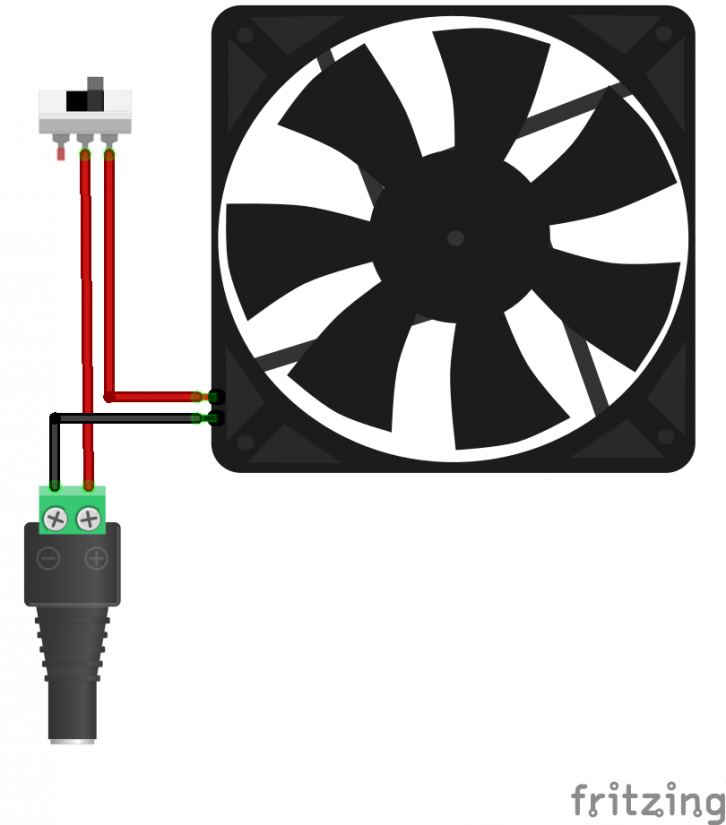
The circuit for the extractor fan is really simple. We have a fan connected to the - (GND) connection of our power supply, and the 12V+ supply is interrupted by out switch. When the circuit is broken, no power flows to the fan and it turns off. But make a connection and the power flows freely and our fan comes to life.
Starting with the DC barrel jack and we need to check the polarity of the power supply. Our supply was centre positive, and this can be easily seen on the sticker present on the supply.
Putting the power supply down for a moment, this means that the centre of our female barrel jack should also be connected to the positive side of the circuit. To test which of the pins from the female barrel jack are connected to the centre, grab a multimeter and set it to continuity mode (or diode test mode) and then touch the probes together. You should hear a beep; see an LED flash; see the screen change and this tells you that the two probes have continuity and are touching. Now take one probe and touch a pin, then take the other probe and touch the centre pin. If it beeps then that pin is connected to the centre pin. Remember this!
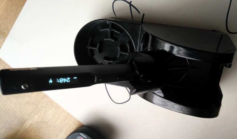
On to soldering and for this part of the project we used the TS100 temperature controlled iron that we reviewed in early 2018. A great iron and well worth your money. But this project can be built using any soldering iron.
Take out your soldering iron; you were warming it up, right? And flow a little solder onto the positive pin. Now put the iron away and grab some wire. We used speaker wire as it was colour coded red for positive and black for negative (GND) and cheap for 100m rolls. Cut a length of wire and strip one end. Separate the wires and twist the exposed red wires, so they are neat. Now using a soldering iron and solder, apply a small amount of solder to the wire so that it keeps its shape. This is called ‘tinning’ and it helps the wire to stay in shape and connect to other soldered items. Cut about 5mm of heat shrink and slide it over the red wire.
Now connect this wire to the centre pin wire by soldering them together. Allow the solder to cool and then slide the heat shrink over so that it covers the exposed wire and the soldered pin. Using a cigarette lighter or hot air gun, gently shrink the heat shrink. Watch your fingers!
Perform the same steps but for the negative (GND) connection of the female DC barrel jack. We used black wire to identify the polarity. The black wire can be left alone for a while as our attention turns to creating the switch circuit.
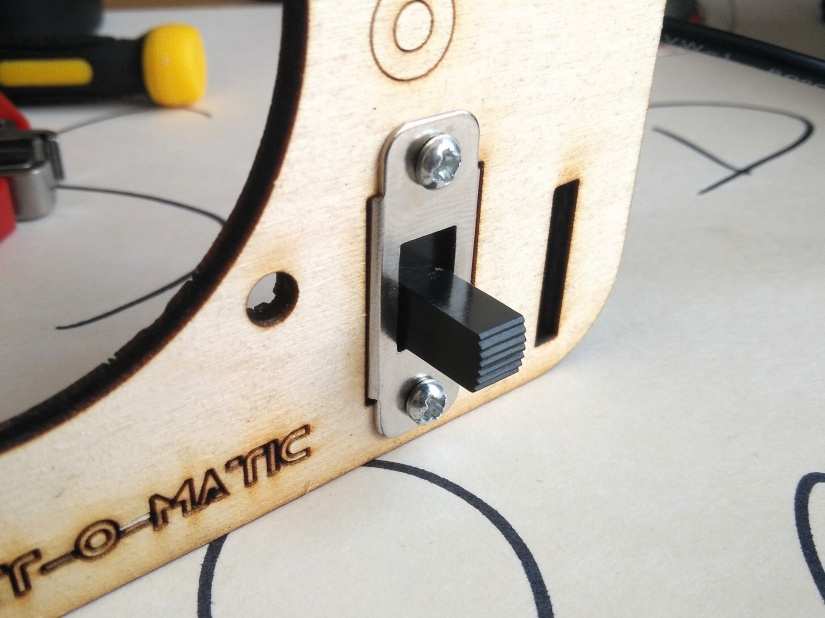
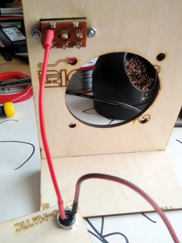
Secure the switch to the front panel using the two M3 10mm machine screws and nuts.
Our switch has two possible connections, on or off (make or break) and we want the switch to connect to our 12V+ (Red) wire. So take the red wire, and cut it to length for your frame. Strip the end of the wire and tin it and also tin one of the contacts of the switch. Cut another 5mm of heat shrink and slide it over the red wire and then attach the red wire to the tinned switch contact. Allow it to cool and slide the heat shrink over the wire and switch contact, then shrink the heat shrink as per the red wire instructions.
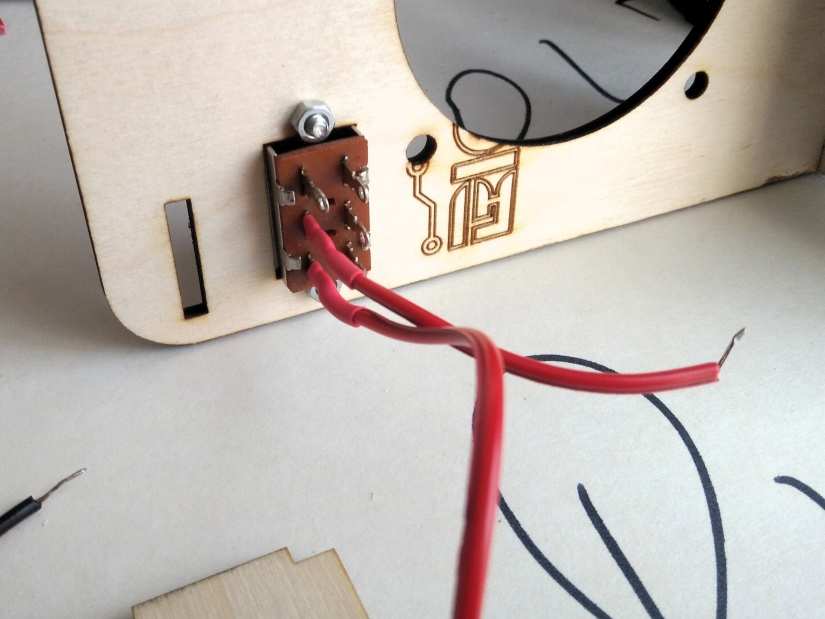
Now we need to do the same thing to the switch contact next to the contact we have just soldered. This will be the on position of our switch and when on, it will connect the fan to the 12V+ supply. So cut a length of red wire, tin it, tin the switch contact, slide on some heat shrink and solder the connection. Then shrink the heat shrink.
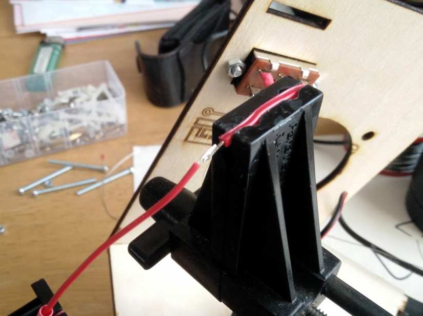
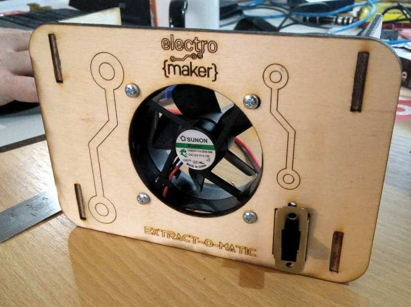
So now we have two wires, the red wire supplies 12V+ via an on/off switch, and the black is our connection to GND. Now we need to connect our fan to the circuit, and typically the fan will have colour coded connections. So chop off the JST connector (white plug) from the fan, strip the wires, tin the wires and slide some heat shrink on the wires. Solder the red wire of the fan, to the red wire from our switch. Then solder the black wire from the fan to the black wire from our DC jack. Shrink the heat shrink to ensure we have safe connections.
Take the four M3 40mm machine screws and thread them through the four 3mm front panel holes and then through the holes of the fan. Secure them in place with the M3 nuts which will, in turn, mount our fan to the front panel!
That is the electronics completed. If you would like to test and be ultra safe, take a 9V PP3 battery and PP3 battery connector to DC male jack, connect it to the DC jack of the extractor and then flick the switch. It should come on and the fan starts sucking … if the fan is blowing then it is on backwards, so take it off and retry.
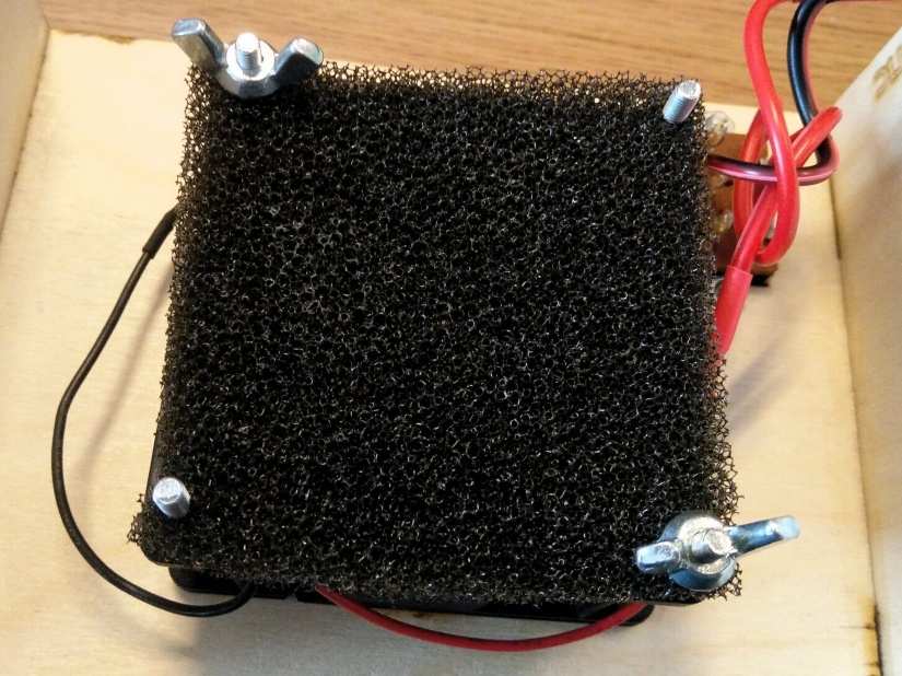
The last step before we take this for a spin is to take the activated carbon foam filter and cut a 70mm square from it. Then force the foam over the exposed machine screws so that it is square and in place. You can use four extra M3 nuts to hold it in place if your wish, or M3 wingnuts for easier replacement.
So now you are ready to connect the extractor fan to the 12V power supply and start soldering without those nasty fumes. Enjoy!

Les Pounder loves hacking and tinkering with Arduino, Raspberry Pi and new technologies. He passes on his skills and discoveries to Electromaker readers via tutorials and reviews.


Leave your feedback...