
Welcome to the ESP32 running EduBlocks!
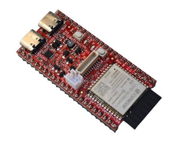
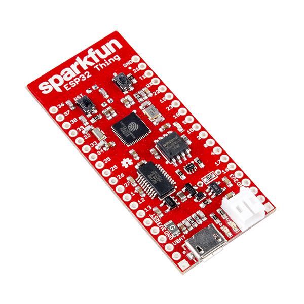
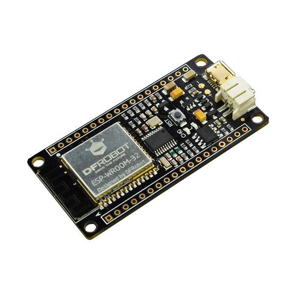
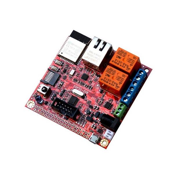
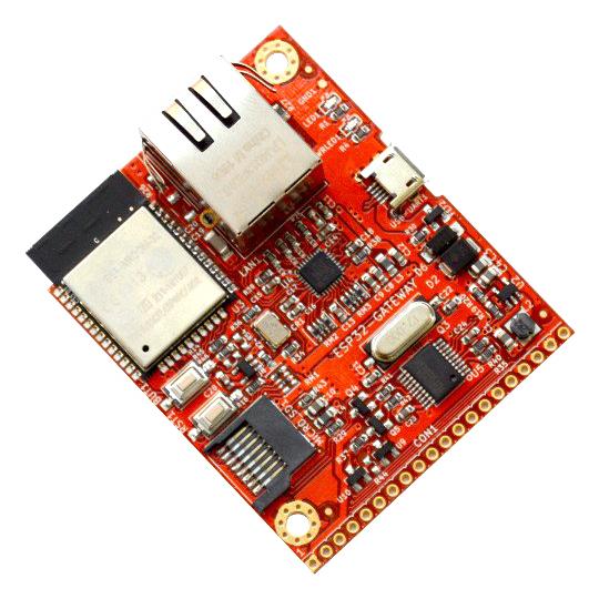
The ESP32 has become the big thing in Internet of Things (IoT) projects. It offers better WiFi, Bluetooth and performance than the ESP8266, and for not much more money! The ESP32 comes in many forms, from a breadboard ‘compatible’ board to a standalone board that has an OLED screen and can be powered from an 18650 battery!
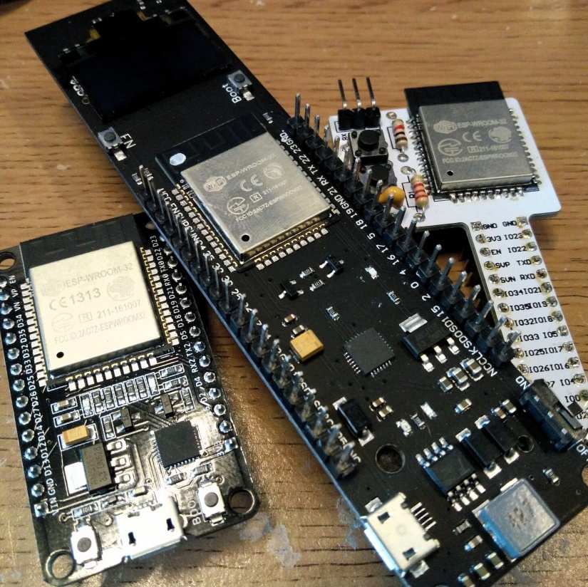
However, no matter which version you may have the board can be a little tricky to work with, and perhaps kids would like to make something with it? Well luckily someone has already answered that call.
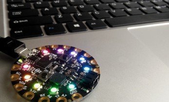
EduBlocks was created by 14-year-old Joshua Lowe as a way for children to move from block languages such as Scratch to text languages, in this case, Python. EduBlocks is available for Raspberry Pi, micro:bit and now the ESP32 thanks to help from local hacker Chris Dell. The ESP32 version uses Micro Python but still retains the simple interface found on other versions. Best of all EduBlocks is free! We had a play with EduBlocks in early 2018, using it to control a neopixel ring via a BBC micro:bit. Great fun!
So let's take EduBlocks on the ESP32 for a spin via this guide where we learn how to write a project that will react to input and of course...blink and LED!
Setting up the ESP32
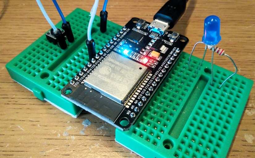
The ESP 32 is rather a large board, and while it may be breadboard compatible, it will engulf most breadboards. We used two mini breadboards and placed them either side of the pins. Then we connected the ESP32 to our Ubuntu 16.04 laptop and started the software install.
Installing EduBlocks
Installing EduBlocks on the ESP32 is rather simple, but we do need to jump through a few hoops. The first step is to go to https://github.com/PrestonHackspace/esp32-micropython and refer to the Requirements section.
Please note that we have followed the Linux install process (which will also work with the Raspberry Pi), but in the Requirements section, there are steps for Windows and Mac users to follow.
We will need to have node.js, Python3 and esptool.py installed to carry on.
So, in a terminal we need to enter the following command to install nodejs.
$ sudo apt update && sudo apt install nodejsIf you are using Ubuntu 16.04, Python 3 comes as standard, but if not then it can be found in your package manager.
The last part of the software install process is to esptool.py, a special Python file that will flash the ESP32 with the EduBlocks install. To use this we need to ensure pip is installed.
$ sudo apt-get install -y python3-pipThen we can install esptools from pip.
$ sudo pip3 install esptoolThe last thing to do is download the esp32-micropython Github repository; this can be done via cloning the repo from the terminal
$ git clone https://github.com/PrestonHackspace/esp32-micropythonAlternatively, you can download the repository to your computer and extract it.
With that complete, we can now start flashing EduBlocks onto our ESP32.
Connect your ESP32 to your computer via a micro USB cable, the board will come to life, and you should see two LEDs (red and blue for us, but your device may differ). Turn on and that indicates the board is working. So, now we need to go back to the terminal and tell Ubuntu where our board is connected, which should be ttyUSB0
$ export ESPTOOL_PORT=/dev/ttyUSB0Then in the same terminal we can issue the next command, which will flash Micropython on to the ESP32. Type in this command, but BEFORE pressing Enter, press and HOLD then Boot button on the ESP32 until you see it connect and start flashing!
$ npm run flash-micropythonOnce complete we can then finally flash EduBlocks on to the ESP32, remember to hold the Boot button before pressing Enter, and wait for it to connect before letting go!
$ npm run flash-sysOnce flashed, the ESP32 will reboot and you will see a new WiFi SSID on your list, it should be clearly identifiable as an ESP device, as the name will start ESP. For example, ours was ESP_0729DD. Select the ESP WiFi SSID and you will be connected.
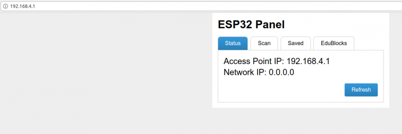
Go to your web browser and visit 192.168.4.1 and you will see the ESP32 Panel, a tool that we can use to see the status of our connection, scan for other WiFi SSID, and run EduBlocks. Click on EduBlocks to launch the application and you will see this screen.
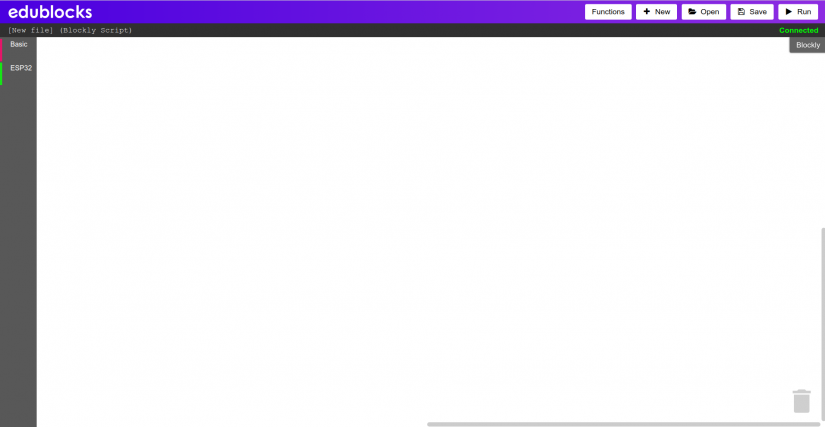
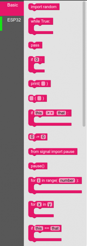
On the left of the screen we can see two menus, Basic and ESP32.
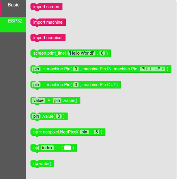
These menus contain the blocks which we will use to code our project in the centre of the screen.
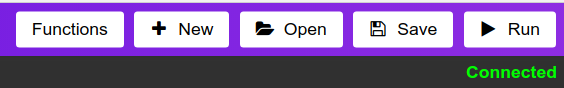
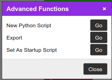
At the top of the screen there are five buttons, Functions, which is used to access advanced features.
Buttons to create a new file, open a file, save your code, and to run the code.
So let’s start writing some code!
Blinking Lights with button input
The first test with any new board and language is always blinking lights! But we shall add a button to trigger our lights to flash.
For this project you will need
- An ESP32 with EduBlocks
- An LED
- A 330 Ohm resistor (Orange, Orange, Black, Gold)
- Breadboards
- 4 x male to male jumper wires
- Push button
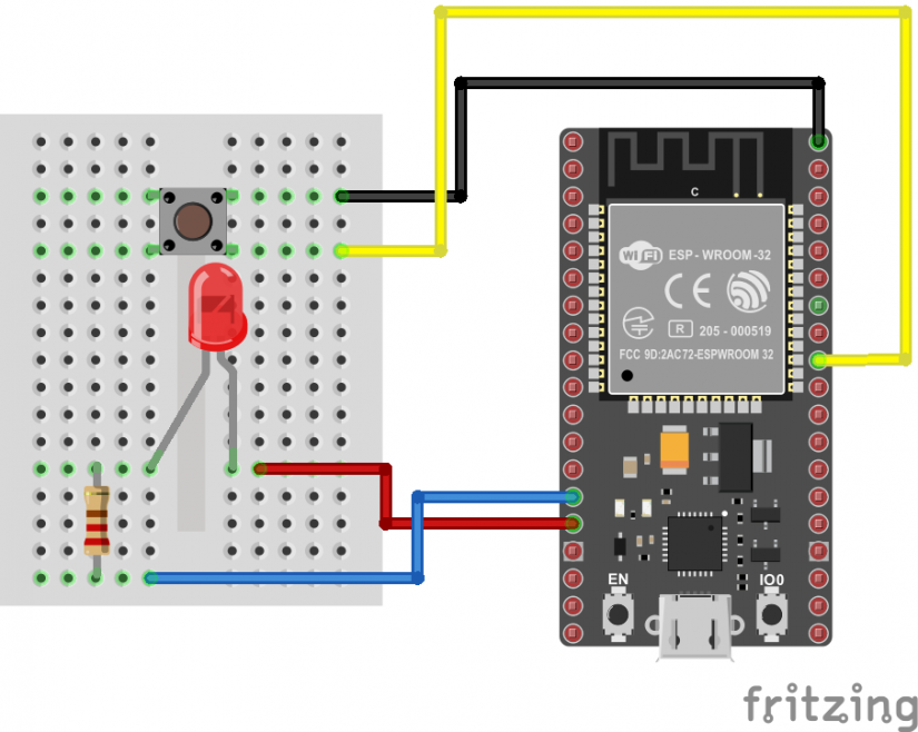
Connect the components as per this diagram. The button is connected to pin 18 and GND (it does not matter which way), and the LED is connected via its long leg to pin 13, and the short leg connects to GND via the 330 Ohm resistor.
Coding the project in EduBlocks
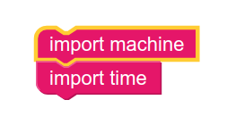
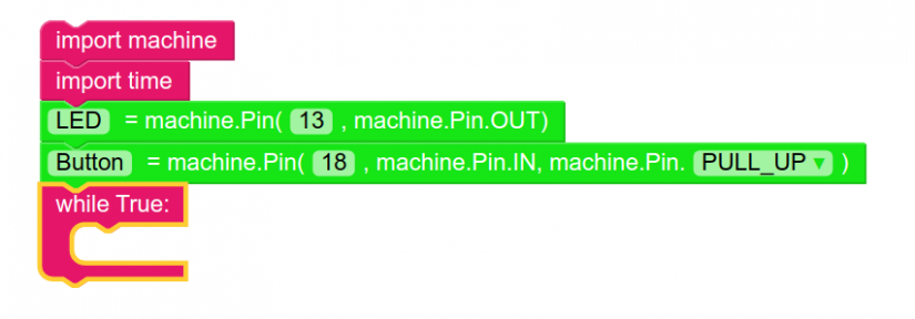
With the hardware connected, we now look to writing the code that will control it. In the EduBlocks editor, we need to start by importing two blocks, the first is ‘import machine’ and this can be found in the ESP32 menu. This block enables our code to communicate with the ESP32 hardware. The second block is ‘import time’ used to control the timing in our code and this can be found in the Basic menu. Join them both together before moving on.
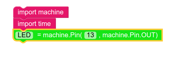
The next block is found in ESP32 and it is ‘pin = machine.Pin(0, machine.Pin.OUT)’ this block will create a variable called ‘pin’ to represent the GPIO pin that we have chosen as an output. In this case we called it LED as our LED will be attached to GPIO 13. Drag the block into your code and edit accordingly.
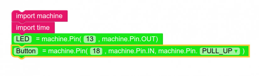
With the output, our LED, setup, we now need to set up out push button connected to GPIO 18. Again we go to ESP32 menu and locate the ‘pin = machine.Pin(0, machine.Pin.In, machine.Pin.PULL_UP)’ block. Drag this block and connect it to the previous. Now we need to Change pin to “Button” and change the GPIO reference from 0 to 18. Now our code knows that we have a button on GPIO 18. But what does PULL_UP mean? Well, that sets the state of GPIO 18 to ON, in other words, it has power. Once we press the push button, it connects GPIO18 to GND causing the pin to go from ON to OFF (HIGH to LOW) and this change in state is used to trigger our code.
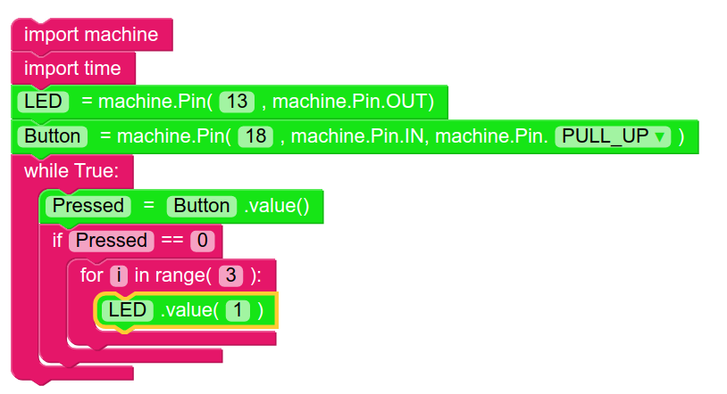
With our LED and push-button setup, we can now move on to the loop that will power our code. From the Basic menu we need to find the ‘while True:’ block and place that under the previous blocks.
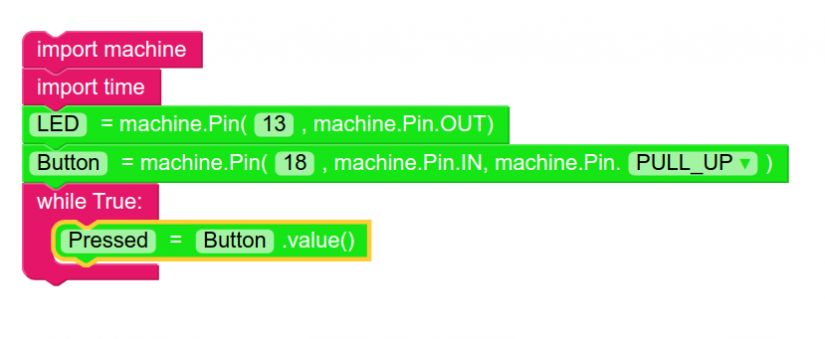
Next we need to check the state of our Button pin (GPIO18) so we go to ESP32 menu and find the ‘value = pin.value()’ block, drag and place the block in to the loop, and change ‘value’ to ‘Pressed’ and ‘pin’ to ‘Button’ (our variable.)
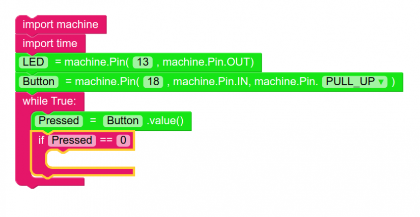
So now that we have the value, constantly updating via the loop, we need a way to test that the state has changed, and so we go to the Basic menu and look for the ‘if this == that’ block. Drag this and place it under the previous block and inside the while True: loop. Change ‘this’ to ‘Pressed’ and ‘that’ to ‘0’.
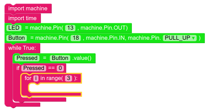
So when the button is pressed, the GPIO 18 (Button) pin goes from HIGH to LOW, 1 to 0, and this triggers the code inside the test to run, and in this case we shall go to the Basic menu and look for ‘for i in range( )’ block, and place this inside the if conditional test. Change the value in ‘( )’ to ‘(3)’ as this will force our code to run three times per press of the button.
So, what shall we do three times when the button is pressed? We shall blink the LED three times of course! For this we need to go into the ESP32 menu and find the ‘pin.value(0)’ block. Drag this inside the for loop, and change the ‘pin’ to ‘LED’ and the ‘(0)’ to ‘(1)’. This will trigger the LED to turn on.
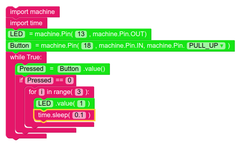
Now that our LED comes on, we need to keep it on for a fixed time. For this we use the ‘time.sleep(1)’ block found in the Basic menu. Drag this so that it connects to the ‘LED.value(1)’ block. Change the value of ‘time.sleep(1)’ to ‘time.sleep(0.1)’ to give us a quick flashing LED.
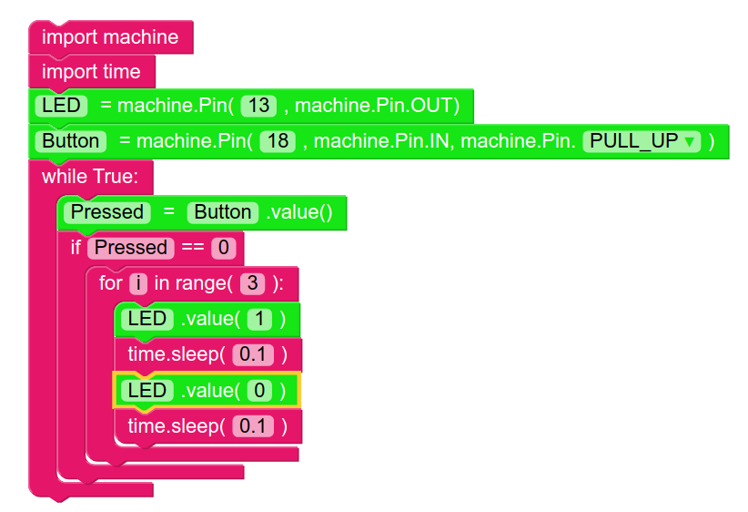
Now we need to write the code to turn off the LED, for the same duration. For this we can right click on the blocks and ‘Duplicate’ each of them and place them in the correct sequence. Ensure that you change the ‘LED.value(1)’ block to ‘LED.value(0)’ to turn off the LED.
With the code in place we now need to save our work, so go ahead and click on the Save button, and name your file ‘blinky’. The file is now saved to the ESP32 and will be available each time the board boots.
So now to test our code we click on Run and the screen fills with a Python shell running our code interactively. So now press the push button on the breadboard, and watch as your LED blinks three times! But why did we blink an LED? Well, the simple reason is that by blinking an LED we have learnt how to control a GPIO pin on the ESP32, and this principle can be put into practice to control a motor via a motor controller. We can use the same pin, the same code and make a motor spin three times at the push of a button. And if we can spin a motor three times, we can do that for two motors, and learn how to make a robot!
When you are finished blinking the LED press ESC on your keyboard to close the shell. The code will still be active in the background, but we can edit the code if needs be.
Is this the end?
We have taken our first tentative steps with EduBlocks, but what more can we do? Well in a future post we shall create a simple robot using EduBlocks on the ESP32 and delve a little deeper in to the world of MicroPython on the ESP32 and learn how we can write Python code directly in the browser and control the screen on an OLED display!

Les Pounder loves hacking and tinkering with Arduino, Raspberry Pi and new technologies. He passes on his skills and discoveries to Electromaker readers via tutorials and reviews.


Leave your feedback...