
So what is Bolt IoT?
The Internet of Things (IoT) is nothing new, it has been with us for over a decade, but in this time we have seen the price of devices fall from hundreds of dollars to less than $10! The ESP8266 (and the newer ESP32) have really shaken the world of IoT from being pretty much a novelty industry (we all remember fridges that tweet and ovens that force us to accept an end user licence agreement) into a citizen science revolution where sensors across the world are monitoring climate change, animal migration patterns and much more.
However, all of these good ideas need a power source and the ESP8266 has become the go-to board largely down to price, and not for its ease of use. But there are boards out there, based on the ESP8266, that offer an easy to use interface that we can use to program the board to do what we want!
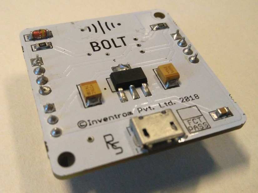
The Bolt IoT platform is one such board, and we had one on the bench and took it for a test drive.
| Parameters | |
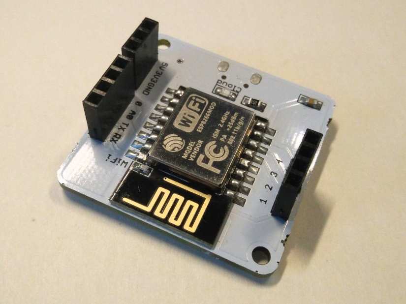
| Connectivity and Processing Module | ESP8266 with custom firmware |
| MCU | 32-bit RISC CPU: Tensilica Xtensa LX106 |
| Power | 5V/1A DC via Micro-USB port or 5V and GND pins |
| Operating Voltage | 3.3V |
| CPU Clock Frequency | 80 MHz |
| MCU Internal Memory | 64 KB of instruction RAM; 96KB of data RAM |
| MCU External Memory | 4 MB Flash memory [QSPI] |
| GPIO pins | 5 Digital pins [3.3V logic] |
| ADC | 1 pin 10 bit ADC [0-1V input] |
| PWM | All 5 Digital pins capable of PWM [Software PWM] |
| Connectivity | |
| WiFi | 802.11 b/g/n |
| Automatic AP mode if not connected to WiFi | |
| WEP/WPA/WPA2 authentication | |
| UART 8-N-1 3.3V TTL UART [using TX, RX, GND pins] [9600 baudrate] |
Setting up Bolt
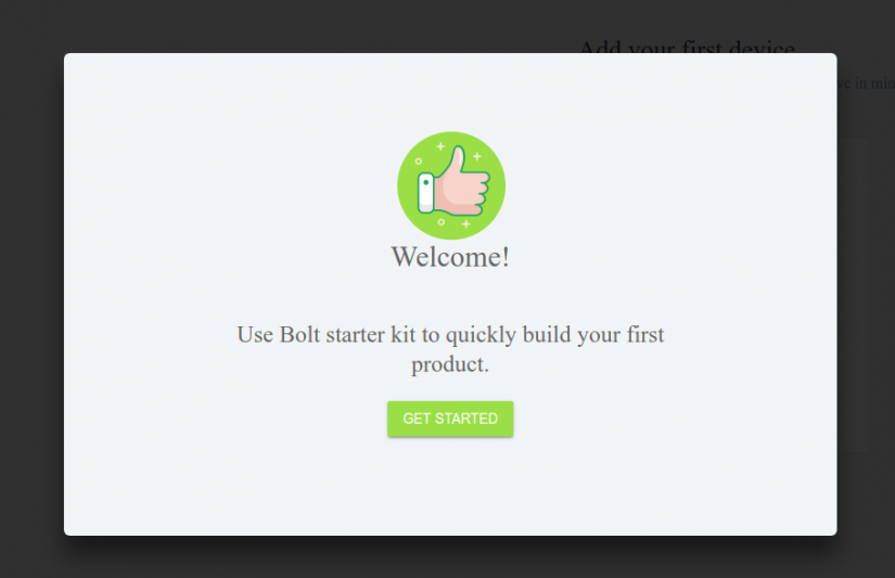
Setting up the Bolt board is simplicity, but there are a number of steps to take. First, we need to go to cloud.boltiot.com and follow the steps to connect our Bolt board to the Internet. You will need an Android or iPhone to connect to the board.
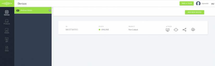
Once the setup is over we take a short tour of the interface and learn how to configure the device, and create ‘products’ which are projects based on the board. Assets are the outputs of the projects we create, for example, the JavaScript code to create a graph. The API contains the API key, the key that enables us to use the Bolt board to gather data or react to input remotely and this key works no matter what supported language we use with it. The last section is Docs and there we can find the help that we may need.
So, the best way to learn about a device is to use it. So let's try to simple projects that will show us how we can use Bolt.
Project 1: Control an LED
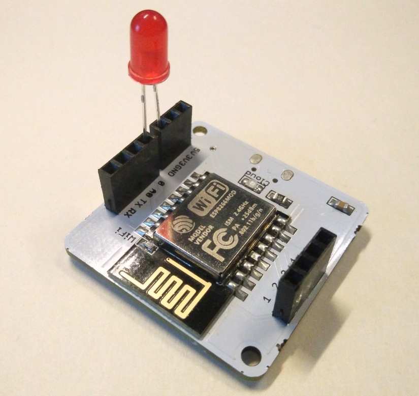
LEDs form the “Hello World” of hardware hacking and this is true of the Bolt IoT board. In this first project we shall control an LED using nothing more than a URL in a web browser.
For this project you will need
- Bolt IoT
- An LED
- A web browser
- Your API key (Found in API, click on the ‘copy’ icon to copy this to the clipboard.
- Your Bolt IoT Device ID
Building the hardware
Our LED has two legs, the long leg (Anode) we shall insert into pin 0 of the Bolt IoT. The short leg (Cathode) we shall insert into the GND pin. Plug in the Bolt to a power source and let it connect to the Internet (The green LED on the board should turn on and show ready.)
Once the Bolt is online, head over to your computer and open a web browser, we shall craft a URL that will turn on the LED.
The URL connects to the Bolt IoT cloud and uses your API key and device ID, then we pass a command to turn on pin 0. This command is called ‘digitalWrite’ and we pass the command the pin number/name and then the state HIGH, which means ‘on’, LOW which means ‘off’.
So here is the URL https://cloud.boltiot.com/remote/YOUR API KEY/digitalWrite?pin=0&state=HIGH&deviceName=YOUR BOLT DEVICE ID
Type this URL, remembering to change the API and Bolt IoT and press Enter. Your LED will come to life! That was simple! Now to turn it off, just change the HIGH in the URL to LOW.
With that simple test, we move on to something a little more complex, this time we shall control a motor using Python.
Project 2: Control a motor using Python 3.
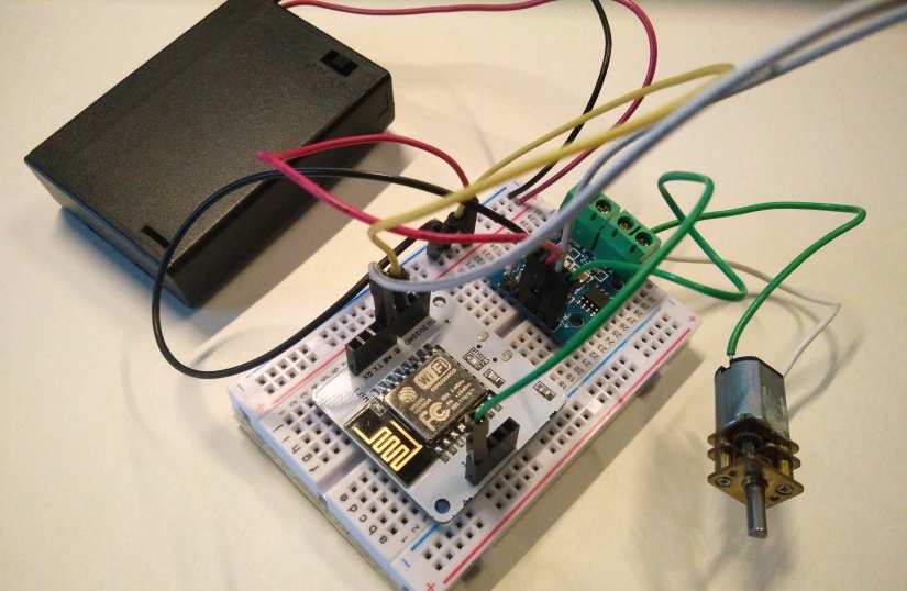
In this project we shall use Python 3 code to remotely control the Bolt IoT device, which will in turn control a motor, connected via a motor control board.
For this project you will need
- Bolt IoT
- 5V DC Motor
- L9110S Motor Controller
- Breadboard With Rails
- 4 x AA battery holder and batteries
- Male to Female Jumper Wires
- A computer running Python 3 with pip3 installed
For this project we shall first connect the two terminals of our DC motor, to the screw terminals for MOTOR A on the L9110S board. Next connect the pins A-1A and A-1B to pins 0 and 1 on the Bolt respectively. To create a common ground connection between the devices we shall now connect the GND of our battery to the GND rail of a breadboard. Then connect the GND of our Bolt IoT to the same GND rail. Lastly, connect the GND from our L9110S. Our last connection is to connect the + wire of our battery to the L9110S; this will provide power to the motor.
Now let's move the attention to our computer. For this next bit we need to be running a computer that has Python 3 installed, and the pip Python package manager. We shall use pip to install the boltiot package.
For Linux systems we will need to type
sudo pip3 install boltiotFor Windows
pip3.exe install boltiotOnce installed we shall open the Python 3 editor IDLE3, installed by default when we install Python3.
In IDLE3 we need to click on File >> New to create a new file. In the new window that opens, click on File >> Save and name the file motor.py and then save. Remember to save often!
Now we start writing the code, and our first two lines import the libraries used to connect our code to the Bolt IoT device (boltiot) and the second library is used to control how long the motor runs for.
from boltiot import Bolt
import time
Next, we create two variables, data storage objects, and in them we store our API key and the Device ID of our Bolt IoT.
api_key = "YOUR API KEY HERE"
d_id = "YOUR DEVICE ID HERE"
Now that we have our API key and Device ID, we need to create an object that connects this code to the device, and for this we create an object called ‘client’ and make the connection.
The last two lines in this section of code create two variables that refer to the motor connections on the L9110S controller. Pin 0 of the Bolt is connected to MotorA1A and Pin 1 is connected to MotorA1B.
motorA1A = 0
motoraA1B = 1
So now that we have set everything up let's start controlling the motor! First we need a loop, and in this case the ‘while True’ loop, a loop that will run forever, will do just nicely.
while True:Now we need to create two lines of code that will send a message to the Bolt board and tell it to turn a MotorA1A LOW and MotorA1B HIGH, in other words, the motor will spin in one direction.
    response = client.digitalWrite(motorA1A, 'LOW')
    response = client.digitalWrite(motorA1B, 'HIGH')
For debug purposes we need to add a print function that will print when the motor is spinning. Then we delay for five seconds, this means the motor turns for five seconds.
    print("spinning")
    time.sleep(5)
And now we shall spin the motor in the opposite direction by reversing the HIGH and LOW state of each pin. Then we print another debug statement, before delaying for a further five seconds.
    response = client.digitalWrite(motorA1A, 'HIGH')
    response = client.digitalWrite(motorA1B, 'LOW')
    print("spinning again")
    time.sleep(5)
With the code complete, click on File >> Save and then click on Run >> Run Module and watch as the motor comes to life! But there is a problem ... the motor timing is way off, so this is something to note for future projects.
The more traditional IoT projects are available from the Docs menu, and that also includes a full API reference guide, handy for future hacks!
So, have a go with the Bolt IoT, it is a lot of fun and very easy to use, no matter what language you may favour.

Les Pounder loves hacking and tinkering with Arduino, Raspberry Pi and new technologies. He passes on his skills and discoveries to Electromaker readers via tutorials and reviews.


Leave your feedback...