
Twitter controlled bubble machine
The Internet of Things is just that, things connected to the Internet. Sometimes they are useful, such as sensors for monitoring health and scientific data. Other times they are trivial/fun. Such as this project.
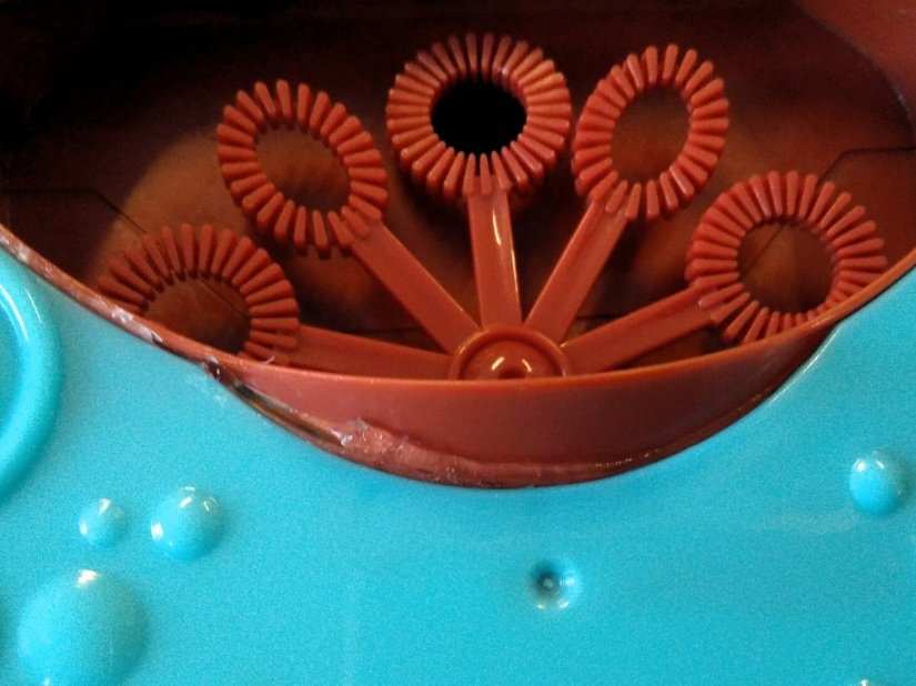
In this project we shall create a Twitter-controlled bubble machine that will react to tweets featuring a certain hashtag and blow bubbles on-demand, from anywhere in the world! Sure this project has no real purpose, but it will enable us to learn a little more about the Internet of Things and have some fun blowing bubbles. To program the project we shall use Node-RED, a simple block-based language that connects nodes to build up a flow of code, think of it as Scratch but on steroids.
We will also introduce a safe, secure, and reliable connector that we shall use to create a simple circuit inside the bubble machine. These connectors are called Wago connectors, and they are insanely cheap, easy to use and safe, even with high voltages.
So without further ado, let's start building our own Twitter controlled bubble machine.
For this project you will need
- A Pi Zero W and the latest Raspbian installed on SD.
- A laptop or computer on the same network as the Pi Zero W
- USB hub for Pi Zero W.
- Keyboard, Mouse
- Mini HDMI connection for the Pi Zero W.
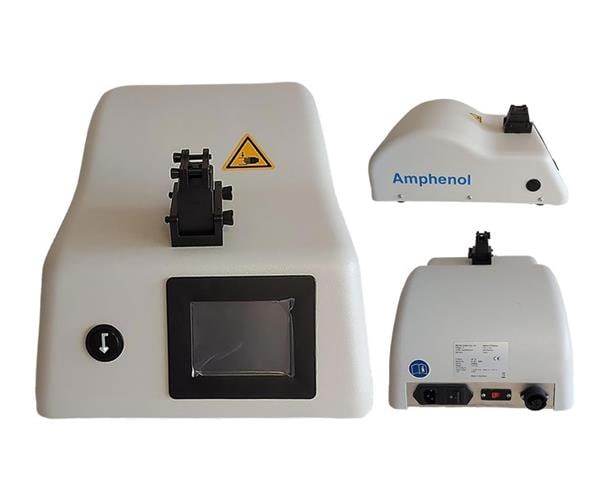
- A Bubble Machine (£2 from Poundland).
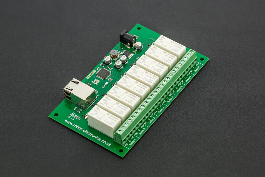
- An L298N motor controller.
- 2 x 3 Pole Wago 221 connectors.
- A 5V 2A power supply.
- Hot glue gun
- Soldering iron and soldering equipment
- 1 x Female to female jumper wire
- Length of speaker wire.
- Wire cutting and stripping tools.

Hardware
The hardware build for this project is relatively straightforward, but we need to take it section by section to ensure we are methodical.
Desoldering the battery connections is the first job, so warm up the soldering iron, and get a fresh piece of solder. Gently heat the joints for the battery at the battery end of the wires. Do this for both wires and mark the polarity (typically red for V+ and black for GND)
Now move up to the switch, and desolder the wire that connects the switch to the motor … at the switch end of the wire! Now remove the switch, it is not needed for this project but keep it in the bits box!
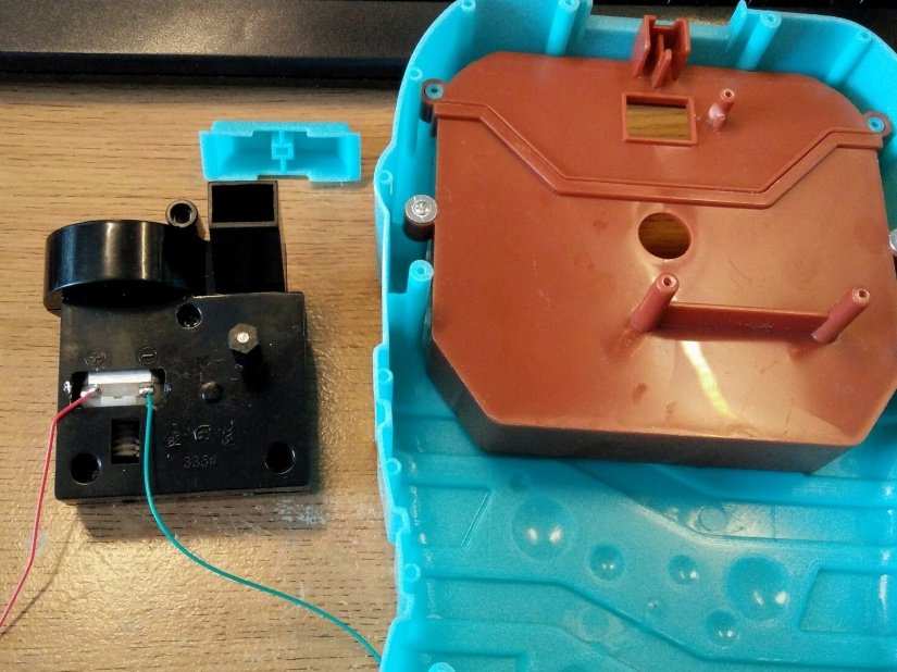
Here is an optional step, you may desolder the wires that connect to the motor. First, you will need to remove three screws from the motor housing so that it comes away from the unit. Also, note that the wand arm is secured at the front of the unit, but it will come off if given a gentle tug. Then desolder the old wires and replace with some better and slightly longer wires.
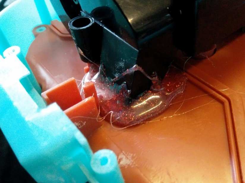
This is also a good time to waterproof the bubble machine and the first thing we need to do is apply a decent amount of hot glue around the vent hole that blows air to make the bubbles. Apply the glue in small amounts and then seat the vent in place. Add a little more glue and slowly build up until it is secure. Screw back into place and let it set for a few minutes.
Now we need to remove the tray that holds the bubble mixture; this has two screws that bite into the brown plastic. Remove the screws and then flip the tray around so that the ‘lip’ of the tray is facing you. Apply a good thick line of flexible glue, to create a water-resistant ridge. We used Fantastic Elastic from 151 Adhesives; this can be found in Poundland in the UK. Secure the tray back in the machine and put the screws back in. We also used some clamps to hold the tray overnight. Waterproofing done and back to the electronics!

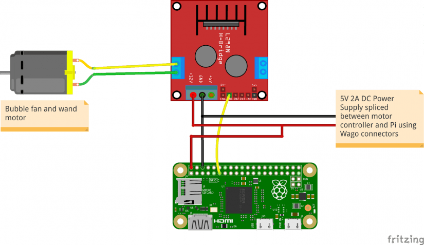
The motor wires will need to be connected to OUT1 and OUT2 screw terminals of the L298N motor controller. The correct polarity is the red wire of the motor to OUT1 and the black/green to OUT2. But do check this before sealing the unit as manufacturers may change this without notice.
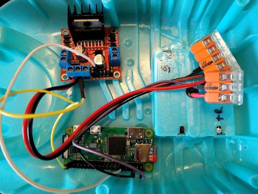
Next, take your USB power supply and cut the USB end off (top tip cut off a few inches before the USB plug end, that way you can recycle the connector in another project) and then strip the cable to reveal the wires underneath. Now using a multimeter determine which connection is 5V and which is GND by plugging in the power supply to the mains and measure the voltage at the wires. Most USB power supplies use red for 5V and black for GND, but a multimeter will definitely confirm this. Do not let the wires touch as this will cause a short and may damage the power supply. Once you have determined the polarity, unplug from the mains and make a note using some tape. Now you can optionally tin the wires with a soldering iron and some solder or just use them as is. But now we need to use the Wago connectors insert the 5V wire from the USB power supply into one pole of a Wago connector, then lock it into place. Do the same for the GND wire into another Wago connector pole.
Now connect some speaker wire from a spare pole on the 5V Wago connector and run this to the 12V screw terminal on the L298N motor controller. Then do the same for the GND connection.
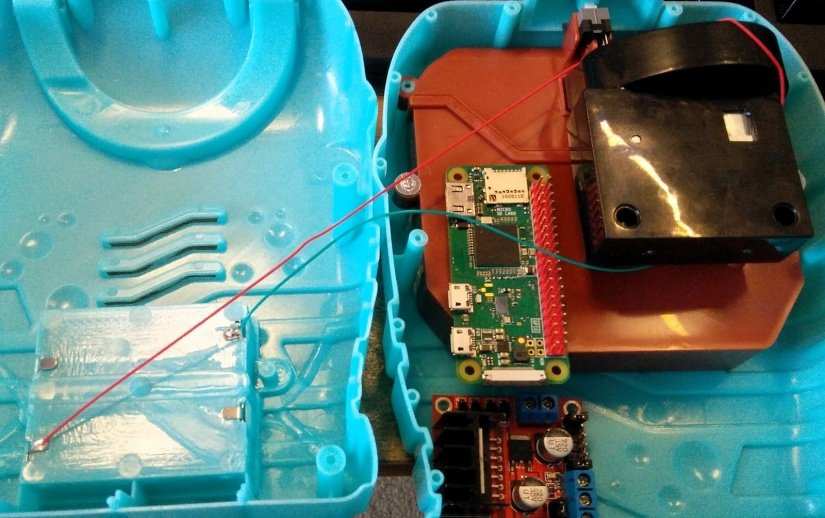
From the Raspberry Pi connect a female to male jumper wire from a 5V pin to a spare pole on the 5V Wago connector. This will supply 5V of power from the USB power supply that we have broken out using Wago connector. Now connect any of the GND pins from the Pi to a spare pole on the GND Wago connector. Lastly, connect another GND from the Pi to the GND terminal on the L298N motor controller.
That’s the hardware completed, on to the code! So boot up the Pi and make sure all your keyboard, mice and mini HDMI leads are connected!
Software
Before we start the project we need to set up the Wi-Fi on our Pi Zero W, this can be handled via the Networking menu, found in the top right of the screen. Simply click on the networking icon and connect to the SSID of your router. If this is the first time that this Pi Zero W has connected to the router, then you will need to tell the Pi Zero W which country you are in. Make a note of the IP address, hover the mouse pointer over the networking icon to see it appear.
The next step is to install the latest version of Node-RED on the Pi Zero W. Why? Well in June the way in which Twitter authentication is handled was changed, and this was reflected in an update for Node-RED. It is really important that you complete this step, otherwise the project will not work. Open a Terminal window and enter the following, it is one line of code wrapped due to its length. Once the code is in the terminal, press Enter to run. It will take approximately 20 minutes to complete, so grab a drink.
bash <(curl -sL https://raw.githubusercontent.com/node-red/raspbian-deb-package/master/resources/update-nodejs-and-nodered)
Once completed, the next and final step in the terminal is to enable Node-RED to run on boot, and for this we enter the following, and press Enter when ready.
sudo systemctl enable nodered.service
Now for good measure reboot the Pi Zero W and let it fully reboot before moving on.
From now on we shall be working from our computer/laptop.
Open your favourite web browser and type in the IP address of your Pi, followed by “:1880”. For example, our Pi was on 192.168.0.8, so in the browser we typed in
192.168.0.8:1880
Press Enter and you will see the Node-RED interface.
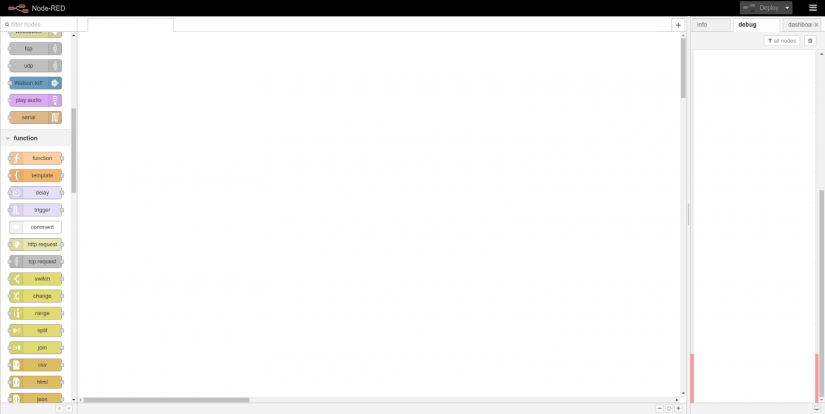
The Interface is split into three sections, and from left to right they are.
The nodes: Where the nodes that make up our code are stored.
The flow: Where nodes are connected to form a flow, similar to an algorithm.
Info / Debug: This is where we can see information on nodes, and view the output of a node /flow.
So let's start by dragging our first node into the flow. This will be a Twitter input node, found in the Social section of nodes. An input node as a grey dot on the right of the node. Drag the node into the flow and double click on the node to edit.
As this is the first time we have used this node, we will need to click on the pen/pencil icon on the right and set up our Twitter account.
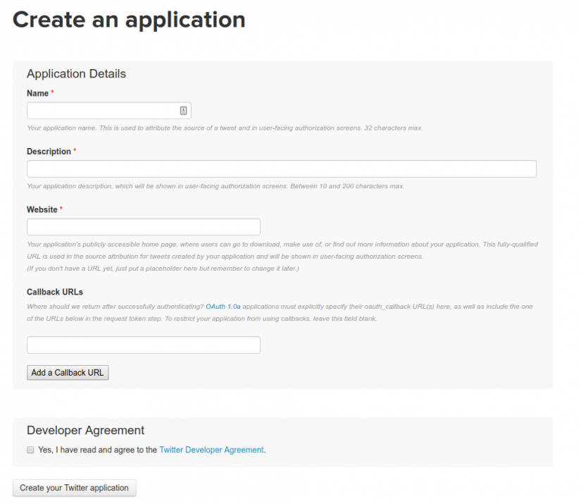
Now click on 1. Create your own application at apps.twitter.com and you will be taken to the Twitter apps website. You may need to log in to your Twitter account. Once their click on “Create New App” and in the next screen complete any of the fields marked with a “*”, for the website, enter your own website/blog, or if you don’t have one try http://electromaker.io Oh and lastly, remember to click on the Developer Agreement tickbox before clicking on ‘Create your Twitter application’ and in a few seconds you will arrive at the settings page for your application.
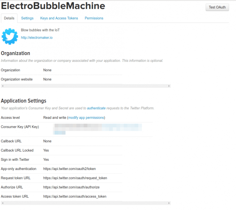
By default, Twitter creates a Consumer Key, which enables us to use the Twitter API, but to really use the API we need to click on the Keys and Access Tokens tab.
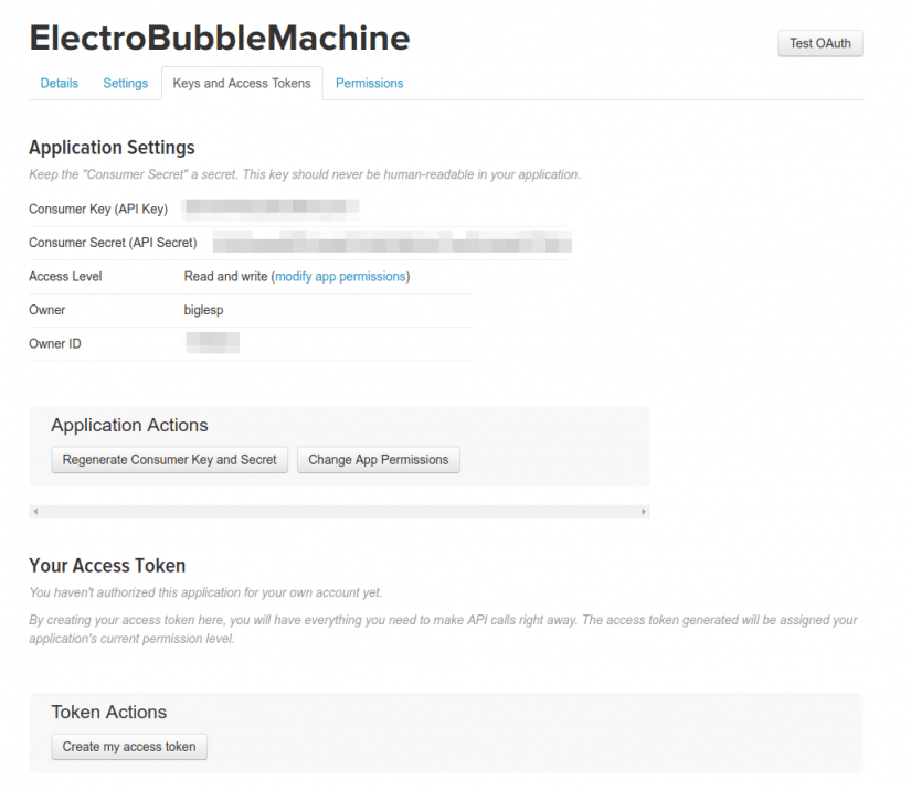
And we can see that as well as a Consumer Key (API Key) we also have a Consumer Secret (API Secret) these enable us to use Twitter via Node-RED but we still need two more pieces of information and these are ‘Access Tokens’. Click on Create Access Token and it will generate the required Token and Token Secret.
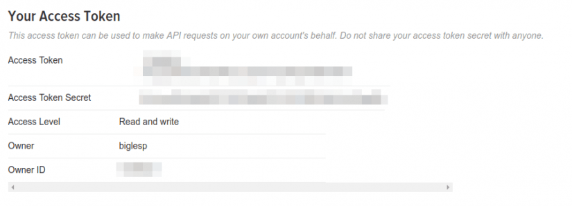
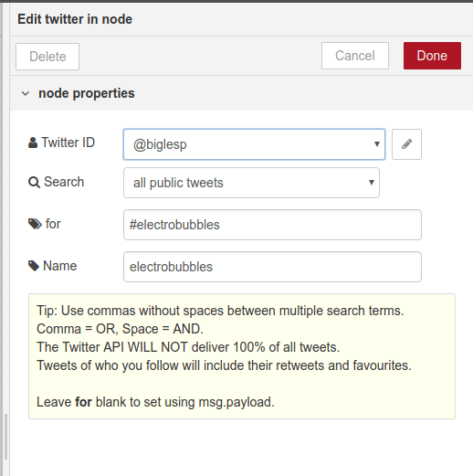
Now that we have the consumer key, consumer secret, access token and access token secret we can take this information and put it into the correct fields in the configuration for our Twitter node.
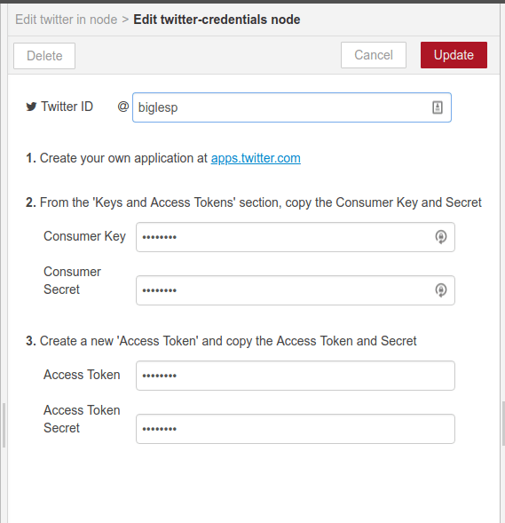
When done click on Update and then configure the node to watch your Twitter account for public tweets featuring a hashtag. Please don’t copy this hashtag, otherwise everyone’s bubble machine will trigger across the world! Although that would be rather cool!
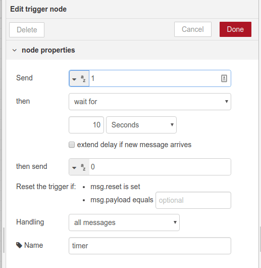
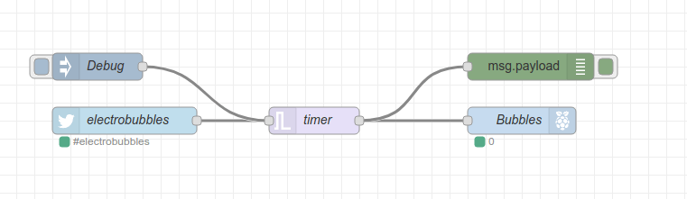
Now we need to create a trigger that will act as a timed switch. Drag the Trigger node from the Function menu and then join the output of our Twitter block to the input of the Trigger node. Left click and drag the wire to connect the nodes.

Double-click on the Trigger node to edit, and for this node we need it to send ‘1’ (programming slang for On/True) and then wait for 10 seconds. This will later turn a GPIO pin on for 10 seconds. Now we tell the Trigger node to send a 0 (Off/False) after those 10 seconds have passed, effectively turning the GPIO pin off. Lastly, we name this node “timer”.
The next block is the rpi.gpio output block found in the Raspberry Pi menu. Drag this block over and connect the output of the trigger, to the input of this block.

Double-click on the rpi.gpio node and edit it so that GPIO17 is selected and it is set to be a digital output. Then tick the ‘initialise pin state’ box and set the initial level of pin to ‘low (0)’ this means the GPIO pin will be turned off by default. Lastly name the pin ‘bubbles’ because this is the pin that is connected to our L298N motor controller that controls the motor which produces bubbles!
That is all of the basic code for this project. You can now click on “Deploy” and in a few seconds your code will be ready. So now is the time to post your tweet containing your hashtag that will trigger the bubbles!
Extra … Extra … Read all about it!
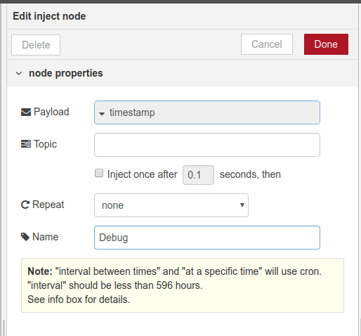
Our basic flow works really well, but there may come a time where we need to diagnose a fault/bug/monumental howler of an issue. This is where we use an inject node, found in the input menu and connect that to the trigger node. Why? Well, this inject node will cause the trigger to activate, and fire our bubbles into the room without the need for us to keep spamming Twitter with tweets which may annoy our followers.
So drag the inject node into the flow and connect it to the trigger node. Then double-click on the inject node and change the name of the node to ‘debug’ nothing else need be changed.
So, now we have the input for our debug, let’s add an output. For this we shall a debug node from the output menu. Drag this node into the flow and connect it to the output of the timer (trigger) node.
OK, that’s it, click on Deploy to write the changes and our code is ready. Click on the tab to the left of the debug node and this will inject the current time into the flow, causing the trigger to activate, which causes the GPIO17 to turn on for 10 seconds, which then causes the motor to start and bubbles to blow! And if we click on the Debug tab on the right-hand side of the screen, we can see the output of the trigger node.
The final code for this project should now look like this.
So, there we have it, our own test function that will double check that our hardware is working, before we spam Twitter with lots of hashtags!

Les Pounder loves hacking and tinkering with Arduino, Raspberry Pi and new technologies. He passes on his skills and discoveries to Electromaker readers via tutorials and reviews.


Leave your feedback...