
What is the Crumble microcontroller and what can we do with it?
When we think of microcontrollers, we think of one of the many hundreds of boards on the market. But when we think of microcontrollers for children, the list is a little shorter, in fact only two boards spring to mind for us, the BBC micro:bit and Codebug. But before these two popular boards there was another board aimed squarely at children, and that was Crumble.
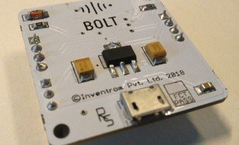
Created by Redfern Electronics in early 2015 the Crumble microcontroller is powered by a PIC16F145S chip, not your typical Atmel or ARM chip. But this chip is easily programmable and available in large number, ideal for popular boards.
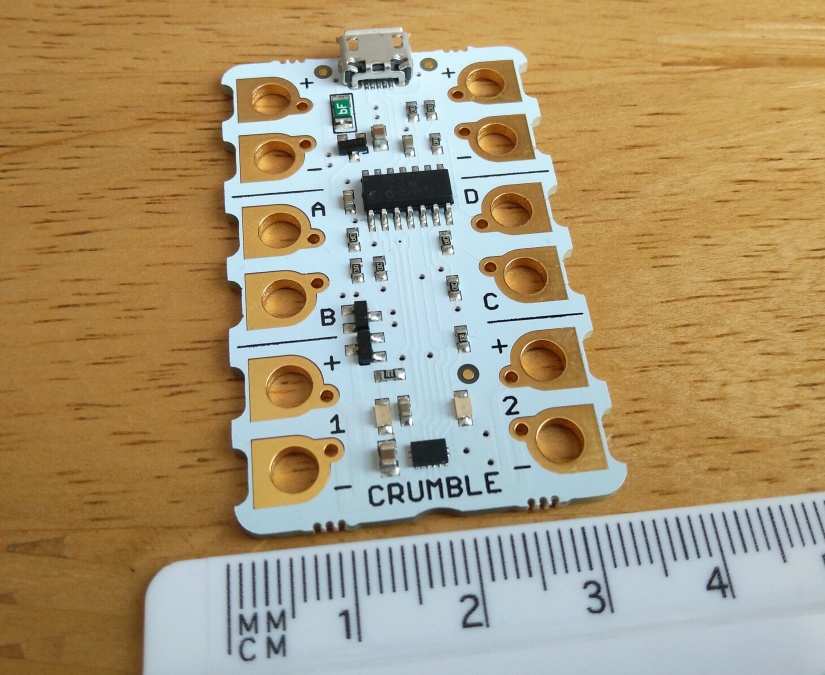
Crumble itself measures 51mm x 34mm and has twelve 4.5/5V compliant GPIO (General Purpose Input/Outputs) and one micro USB, used for power and programming the board.
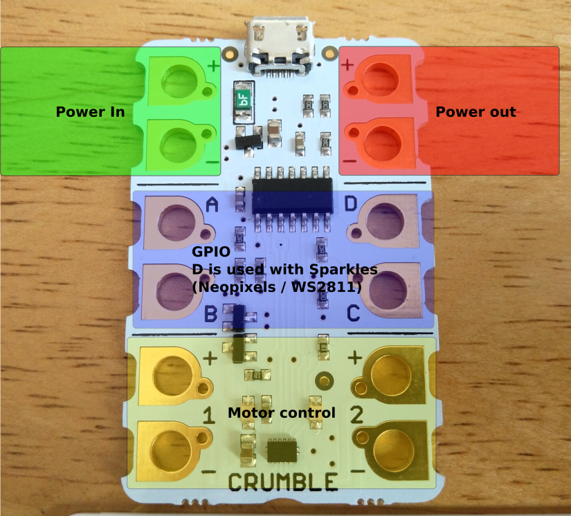
Of the GPIO pins, working from the top of the board we have two power input GPIO (Green box) used for connection to an external power source (rated between 4.5V and 5.5V) and this is reflected in Power Out GPIO in the right of the board (Red).
The next four GPIO (Blue) are A, B, C, D and these can be set as inputs or outputs and they can work digitally or as analog ports.
The last four GPIO (Yellow) are reserved for use with DC motors as Crumble comes with a built-in H bridge motor controller enabling us to control motors both forwards and backwards.
Connections to the GPIO are made via crocodile clips, or if you need a more sturdy/permanent connection, then you can use M4 screws and ring crimps quite easily.
To code the board we need to download the Crumble software from their website. This free download is available for Windows, Mac and Linux devices, including the Raspberry Pi.
The Crumble software is very similar to Scratch, in that we have blocks of code that make up a sequence/algorithm. But it does have a few little idiosyncrasies; chiefly there is a block called ‘program start’ which is used in place of Scratch’s ‘Green Flag’, the next difference is that when using comparison operator blocks, we cannot use float values, only integers are accepted. Lastly Crumble has its own WS2811 (neopixel) LEDs called ‘sparkles’ and these are found in the ‘Sparkles’ menu.
Crumble also has its own range of compatible components, designed for use with crocodile clips. We have line follower Widgets, push buttons, sparkles (individual, matrix or as a baton for any budding Jedi) other common components adapted for use with Crumble. But if you already have a selection of components that you would like to use with Crumble, then you can but a pack of five ‘crumbliser’ boards that convert breadboard pitch components for use with Crumble.
Using Crumble in a project
But the proof of the pudding is in the eating (ahem), and with Crumble that is also true so let's take it for a test drive and create a parking sensor project that kids can easily use in their playtime!
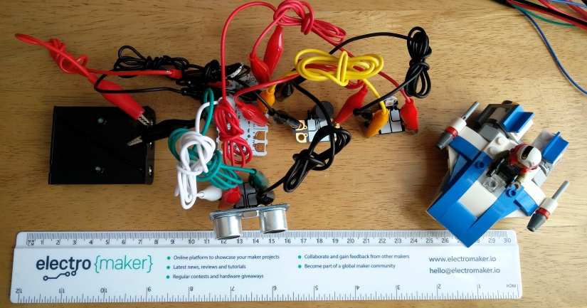
For this project you will need
- A Crumble
- Micro USB cable
- Crumble-friendly Switched Battery Box
- Batteries
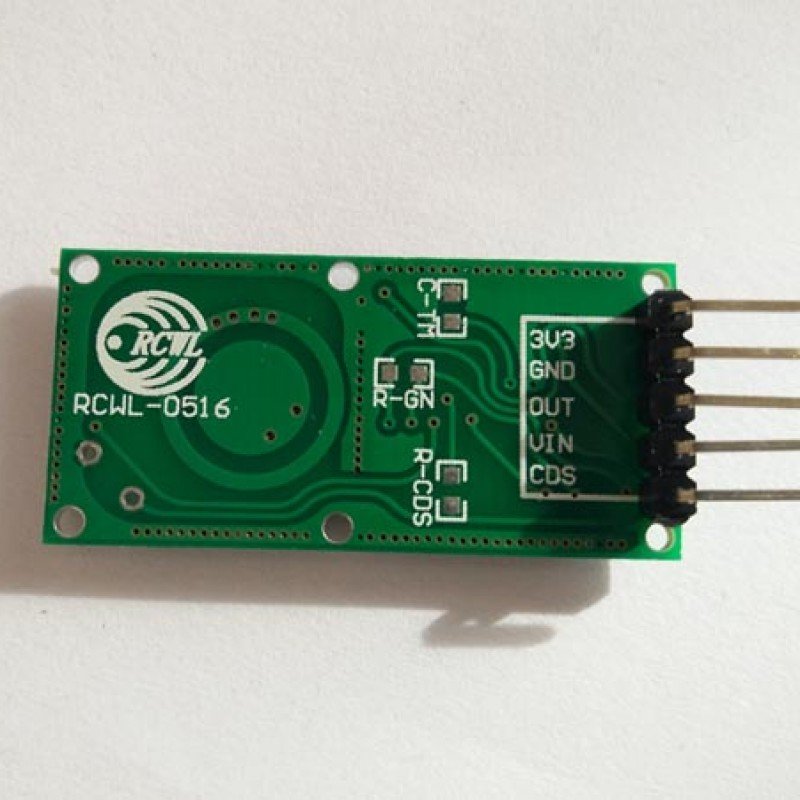
- Ultrasonic Distance Measuring Sensor
- Single sparkle
- Crumblisers
- Buzzer (Or buy the Crumble Friendly Components pack)
- Lots of crocodile clips
Let’s get started.
Hardware Build
Creating a circuit using Crumble is simple, but a little different as we will use crocodile clips to make the connections.
Battery Connections
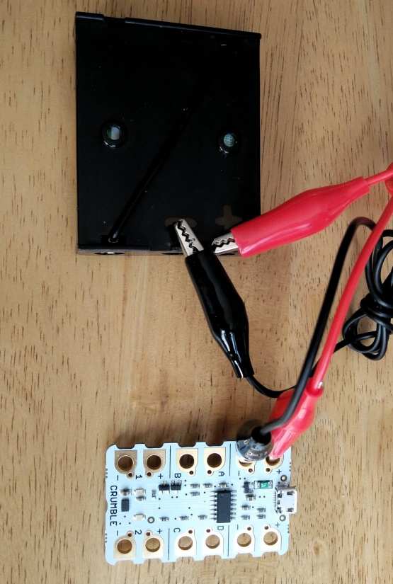
From the Crumble-friendly Switched Battery Box connect the + terminal to the + power input top left of the board) then do the same with the - terminal to the - power input on Crumble. Do not flick the switch just yet.
Buzzer Connections
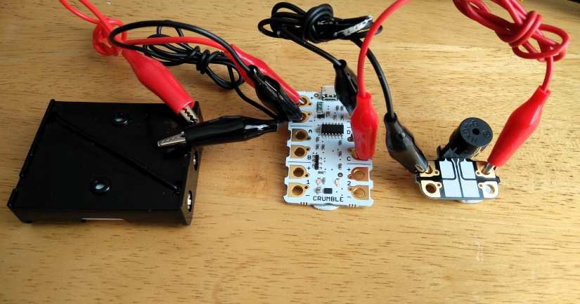
Connect the + terminal of the buzzer (long leg) to GPIO C on the Crumble. Connect the other leg too - on the power output. If you are using a crumbiliser, then check that the buzzer is firmly held in place and that your crocodile clips are connected correctly.
Sparkle Connections
Sparkles have six connectors. Look for -> D side of the connections and connect GPIO D from the Crumble to -> D on the sparkle. Then connect + power output from the Crumble, to the + on the same side as the -> D connection we have just made. Then connect the - power output from the Crumble to the free - connection on the sparkle. We didn’t have a sparkle, so we used a crumbliser to create our own using a neopixel.
![]()
Sensor Connections
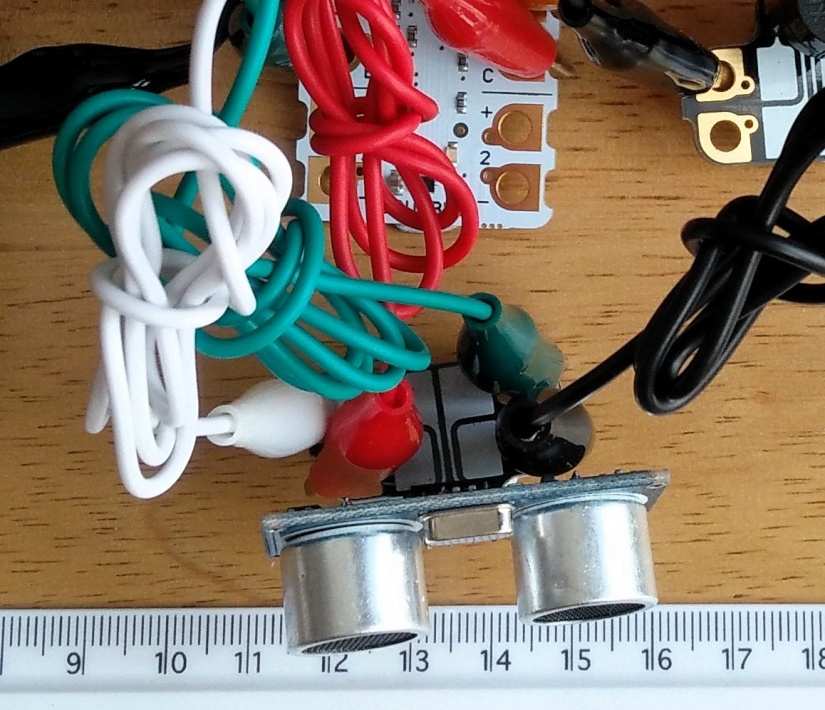
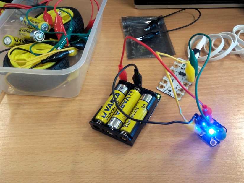
Our ultrasonic sensor has four connections. We need to connect the + and - connections to the + and - power outputs on the Crumble board. Next, connect the Trigger of the sensor to GPIO A on the Crumble, and then connect the Echo pin to GPIO B. All of the connections have now been made and we can now start coding the project.
Check all of your connections to ensure that they look like those in the image above.
Writing the code
On your computer go to the Crumble website and download the software for your operating system.
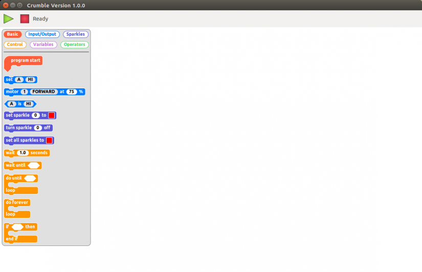
Install the software and then open it to reveal the Crumble editor. On the left of the screen are the blocks that can be used to write the code, and these blocks can be filtered by clicking on the filters at the top of the screen, To code we drag boxes from this left section into the main coding area. And from there we can run/stop code by clicking on the green triangle (play) and red square (Stop)
We shall start the code for this project by dragging two blocks from the Basic filter. These are ‘program start’ used to start the code, and then we shall drag the ‘do forever loop’ and connect it to the ‘program start’ block.
Now let’s drag two ‘if..endif’ and place them inside the main loop. These will form the basis of two tests later in the code.
Our If conditional tests will be used to check that the distance of our car from the sensor, so that means we need to use a new block from ‘Operators’ called ‘__ and __ ‘ for each test.
Going back to the Operators filter and we need to drag operators used to compare if a value is less than (<) or greater than (>) a value.
But what are we going to put in these new blocks? Well For each operator block we will place a ‘distance (cm)’ block from the Input/Output filter. This is a block that will send a pulse of ultra-high frequency sound from the ultrasonic sensor which is triggered using GPIO A on the Crumble (trigger) and then using some internal calculations the receiving pulse, bounced off an object (Echo) is received via GPIO B and this gives us a distance in centimeters. For the first test we will see if the distance of our car is less than 10 centimeters, but greater than five centimeters.
So, what will happen if the car is less than 10cm away but greater than 5cm? Well, we need to warn the driver so let’s turn the sparkle (Neopixel) connected at GPIO D Yellow so that they can see they are near!
The driver has not seen the yellow sparkle! What do we do? Well, let's create a simple ‘beep’ using our buzzer. This will beep every 0.2 seconds and beep for 0.2 seconds. For this we need to turn GPIO C on (HI) then use a ‘wait’ block to create the delay. Then we turn the buzzer off (GPIO C LO) for the same duration, we also turn off the yellow sparkle, causing it to flash.
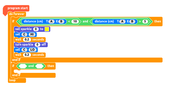
That is all of the code for this first test and your code should look like this
Now let's create the code for the second condition to test. This time we need to check if the car is less than 5 centimeters away, and greater than 2 centimeters from the sensor. This code is nearly the same as the previous test, except for the distances used in the test, the colour of the sparkle and the wait is now only 0.1, giving us a quicker beep and flashing red sparkle.
Complete Code Listing
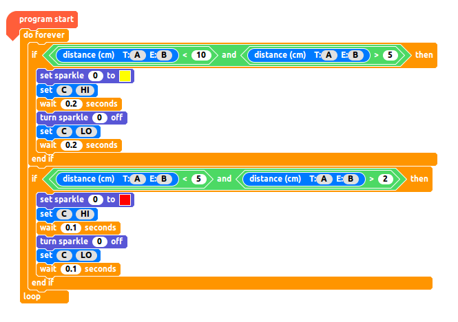
All of the code for this project should look like this. Double-check your code before moving on.
Testing The Code
With the code completed, and the hardware connected. Let’s click on the green triangle (play) to flash the code onto the Crumble. Now turn on the battery pack, and after a few seconds place your hand about 30cm in front of the sensor and slowly move your hand nearer and nearer until you trigger the flashing yellow sparkle and buzzer. Then move even closer until the sparkle turns red and the buzzer beeps quicker!
You’ve made it! You have created a parking sensor for playtime. Now attach it to your bike, go-kart, soapbox racer and go and enjoy the summer … safely!

Les Pounder loves hacking and tinkering with Arduino, Raspberry Pi and new technologies. He passes on his skills and discoveries to Electromaker readers via tutorials and reviews.


Leave your feedback...