
Using a Doppler radar sensor with the Raspberry Pi
There are many sensors on the market for the Raspberry Pi, Arduino and other single board computers/microcontrollers. But the RCWL-0516 is something new and exciting in that it offers the simplicity of a PIR sensor but with a greater range and ability to detect through objects, yet it still only retails for a few dollars from China.
What is the RCWL-0516?
The RCWL-0516 is a Doppler radar microwave motion sensor, in other words it works in a similar manner to the typical BISS0001 PIR sensor that everyone has in their bits box. But rather than detecting movement using the infrared energy, it uses changes in the transmitting frequency to determine if an object is in its path. The RCWL-0516 has a range of around 7m – plenty of range for even the most demanding project.
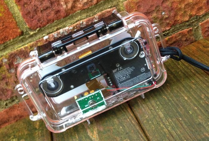
So, is it better than the humble PIR sensor? Well, quite frankly, yes it is, for one simple reason, it can work from inside a case, meaning it can be stored in a waterproof case, used as a trail cam, and remain safe and dry. Unlike the PIR which cannot operate through even a transparent case as that will block the infrared energy.
So, what can the RCWL-0516 be used for? If you need to trigger a camera to life, detect animals or humans entering a room or open space, or activate a robot when it detects a user, well this is the sensor for you.
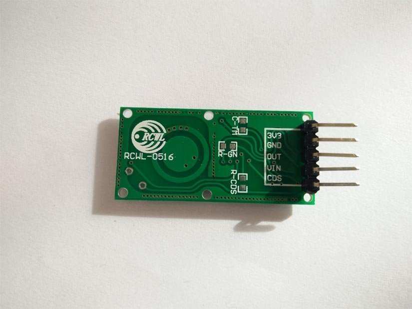
RCWL-0516 Pinout
The RCWL-0516 has only five pins
- 3V3 - A regulated 3.3V output.
- GND - Ground
- OUT - Resting value is LOW (0V) but when motion is detected it goes to HIGH (3.3V)
- VIN - Supply voltage between 4 and 28V (We connect this to the 5V of the Pi)
- CDS - A bit of an enigma here, it appears that this is for a light sensor, but not much else is known.
Let's take it for a test drive
To illustrate how to use the RCWL-0516 we’ve written an application that will take a picture using the official Raspberry Pi camera each time the sensor is triggered. The filename for the image will be the timestamp of the time and date the sensor was triggered.
Bill Of Materials
- Any model of Raspberry Pi
- Raspberry Pi Camera
- RCWL-0516
- 3 x Female to Female Jumper wires
All of the code for this project can be downloaded from Github, and it includes a bonus version which uses polling, via an infinite loop.
https://github.com/lesp/electromaker-RCWL-0516
Hardware Build
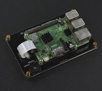
Before we turn on the Raspberry Pi, we first need to connect the camera to the CSI port, which is between the HDMI and composite port of the Raspberry Pi (Pi Zero owners, yours is at the end of the board, but you will need an adapter to connect). Release the plastic retainer on the CSI port and then insert the camera cable into CSI port so that the blue tape is facing the Ethernet port. Once in secure the plastic retainer to ensure that the cable is connected.
For the next part of the build, we will need to connect the RCWL-0516 to the GPIO of our Pi. The sensor requires a little soldering to breakout the pins, but it shouldn’t prove too taxing.
The connections between the Pi and RCWL-0516 are as follows.
Raspberry Pi RCWL-0516
- 5V VIN
- GND GND
- GPIO17 OUT
Software Build
With the hardware setup complete, let's boot up the Raspberry Pi to the desktop. But before we can start writing code we need to configure and test our camera.
First, we need to configure the Camera interface, and for this we need to use the Raspberry Pi Configuration application, found in the Preferences section of the main menu. 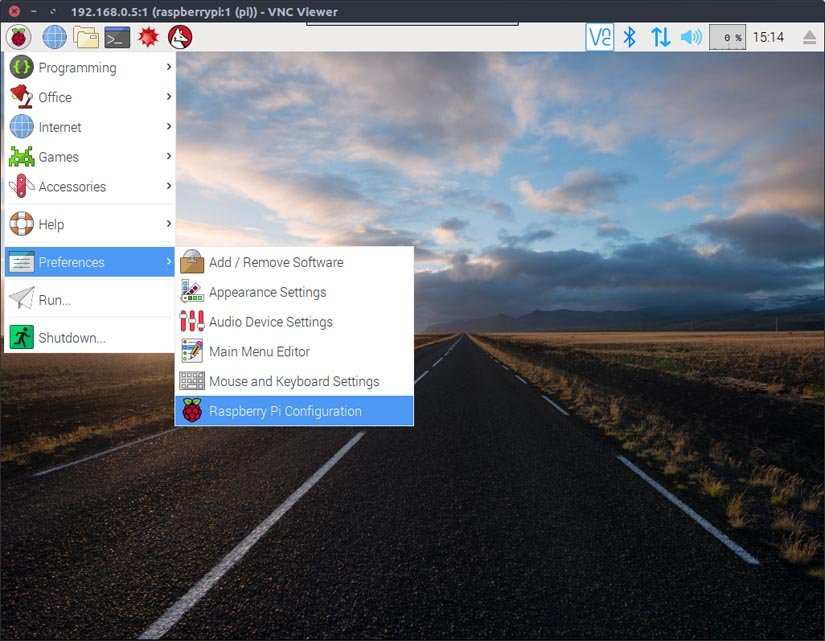
Once the application has opened, click on the Interfaces tab and then enable the Camera interface. You will need to reboot for the changes to take effect.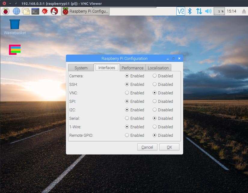
You will see the preview window appear and after five seconds your photo will be taken. You can use the File Manager to find your photo and see how it looks. After a successful test, let's start writing some Python code!
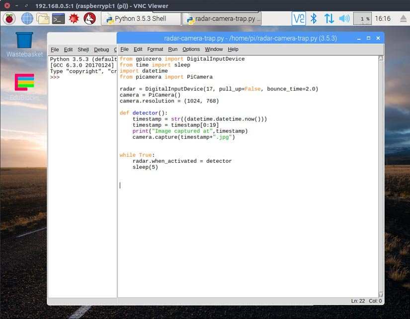
For this project we used IDLE3 which can be found in the Programming menu. Create a new file and call it radar-camera-trap-.py also remember to save often, to minimise the risk of losing code.
The first lines of Python code handle importing the libraries that will be used in the project. We import the DigitalInputDevice class from GPIO Zero, which we shall use to create an object that represents our RCWL-0516 sensor. Then we import datetime, which will be used to create the timestamp filename. Then we import the Picamera library to control our camera before lastly importing the pause function from the signal library used to prevent our code from exiting.
from gpiozero import DigitalInputDevice

import datetime

from picamera import PiCamera

from signal import pause
Now let's move on to creating objects that will contain the configuration of our RCWL-0516 radar sensor and the camera.
Our first object is called radar and this is our RCWL-0516 sensor connected to the GPIO of our Raspberry Pi at GPIO 17. This sensor has a resting state of 0V (LOW) for its output pin and so we need to make sure that our GPIO pin is also low, so we set the pull-up resistor for GPIO17 to False, which will pull the pin low. Then we set the bounce time, the time it takes for the sensor to reset after detecting movement, to 2.0 seconds. Enough time for a clear reset.
radar = DigitalInputDevice(17, pull_up=False, bounce_time=2.0)
Our next object is a connection to the camera and we set the resolution of the camera to 1024x768, this gives us a large enough image, without generating lots of large images on the SD card.
camera = PiCamera()

camera.resolution = (1024, 768)
Our next section is to create a function that will be called when the radar is triggered. This function is called detector and inside the function we have four lines of code.
def detector():
To create the timestamp filename, we first need to get the current time and convert it to a string.
timestamp = str((datetime.datetime.now()))
Now the timestamp data is rather verbose and includes time down to the millisecond, so let's use string slicing to cut out and update the timestamp variable with the date and the time down to the second.
timestamp = timestamp[0:19]
Then we print the timestamp to the screen. This is handy to debug and show that the code is working.
print("Image captured at",timestamp)
Our last line inside the function is to capture the image with our camera and use the timestamp as the filename.
camera.capture(timestamp+".jpg")
Now out of our function, we have only two lines of code to add. When the RCWL-0516 detects movement it will activate and the output pin will go from LOW to HIGH for two seconds. When this change of state happens it will call the detector function that we have just created. Notice that we call the function without its parentheses, as this creates a reference to the function which is then called when the radar detects movement. The last line of code is a pause that prevents our Python code from exiting and ensures that we can keep waiting for the sensor to be triggered.
radar.when_activated = detector

pause()
Save the code and when ready click on Run >> Run Module to test.
Now wave your hand over the sensor and you will see the Python shell output informing you that a picture has been taken. Open the File Manager and you will see the picture is already there. Have fun using your new radar sensor camera trap . . . what images will you capture?


Les Pounder loves hacking and tinkering with Arduino, Raspberry Pi and new technologies. He passes on his skills and discoveries to Electromaker readers via tutorials and reviews.


Leave your feedback...