
DIY Retro Arcade Cabinet - Part 1 - Planning
DIY Retro Arcade Cabinet - Introduction
DIY Retro Arcade Cabinet - Part 1 - Planning
DIY Retro Arcade Cabinet - Part 2 - Component Selection
DIY Retro Arcade Cabinet - Part 3 - Laser Cutting
DIY Retro Arcade Cabinet - Part 4 - Assembly and Configuration
In the 1980s there was one place to go if you wanted the latest games, your local arcade. These arcades buzzed with electronic lights and sounds, designed to entice us to play the latest games. Classics such as Pacman, Space Invaders, Chase HQ, Operation Wolf offered an alternate reality for only 20p!
With the rise of the 16-bit home console in the 1990s, the humble arcade saw fewer people and games. Sadly, they are now very rare across the world.
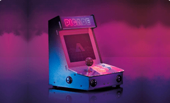
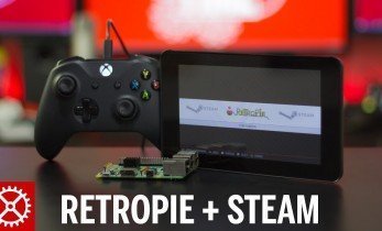
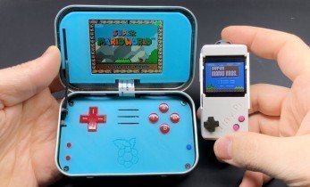
But thanks to emulation we can relive those golden days and in this series of posts we shall create our own miniature cabinet using the Raspberry Pi Zero.
So how are we going to build the cabinet?
Our cabinet will be made from A4 sheets of plywood, cut using the K40 laser cutter. The main frame will be cut from 6mm sheets of plywood, and small cross-pieces will be cut from 3mm plywood. There will also be an acrylic screen protector used to prevent damage to the screen.
To design the cabinet we referenced a previous project.
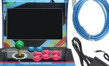
In mid-2017 we purchased a “Nintendo Switch Arcade Cabinet Kit” from Amazon for around $20, when it arrived, well, it didn’t inspire too much hope.
The “wood” used is about 2mm thick and brittle, and the unit is held together with elastic bands.
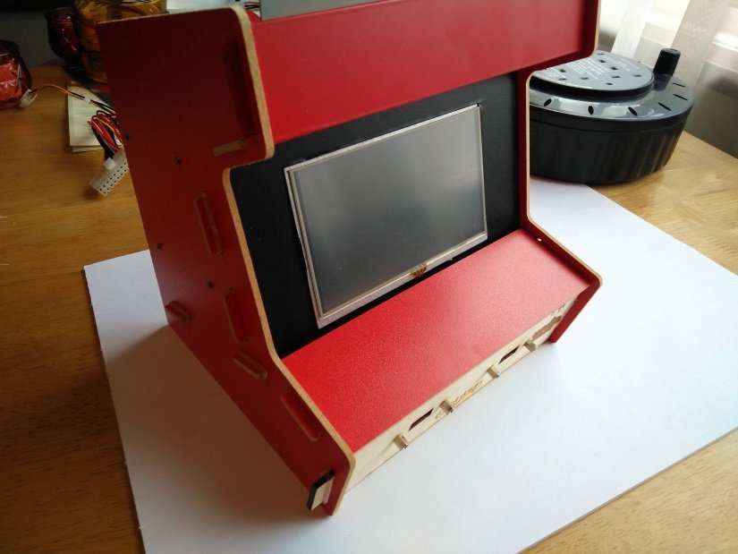
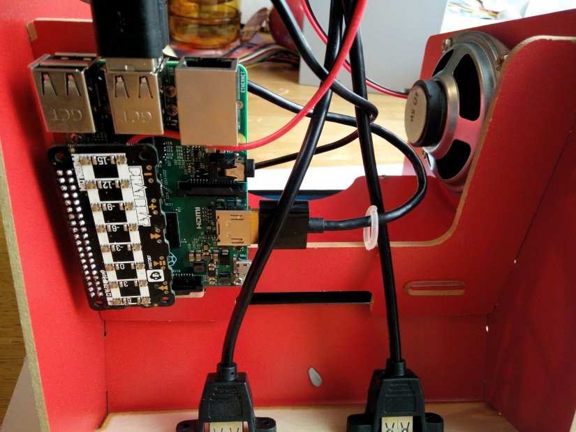
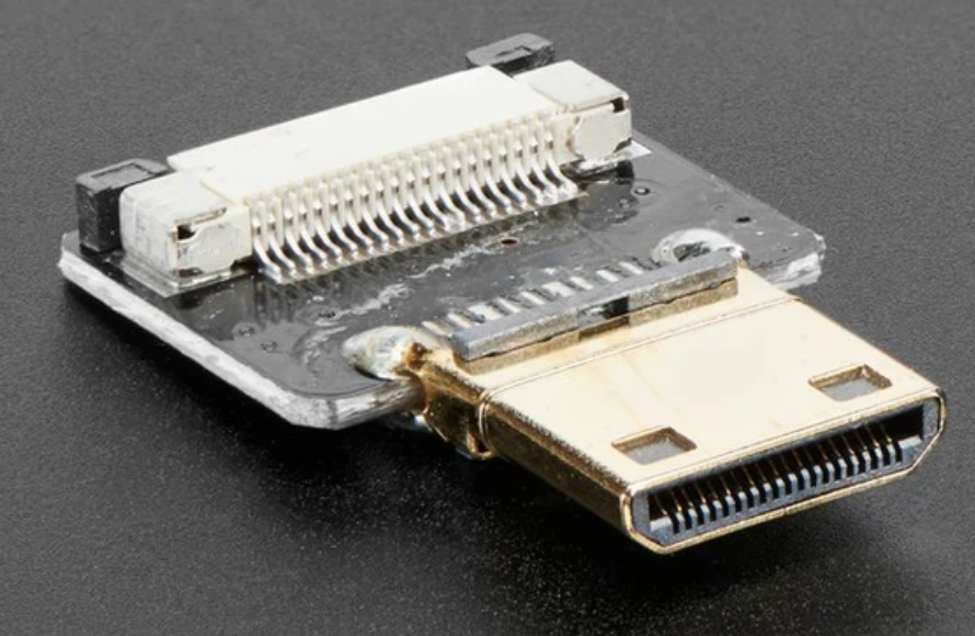
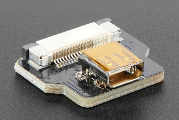
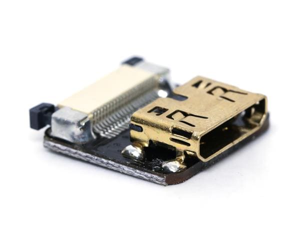
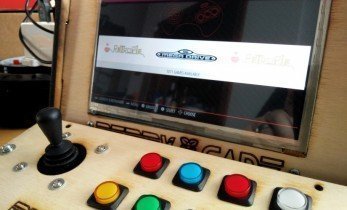
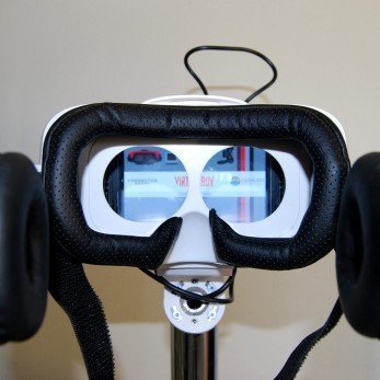
But undeterred, we put the unit together to see what it was like. OK, it was a little flimsy, but there was potential! So we created a test fit using components that we had lying around, such as a 5” 800 x 480 HDMI screen, a Pi 2, a PhatBeat speaker kit from Pimoroni and a USB breakout connector.
Assembling the kit without the use of a laser cutter was OK, but sadly we lacked the precision necessary to measure the points to drill the wood to secure the screen to the frame. It still worked, and with the use of a carefully cut piece of foamcore the sins were hidden!
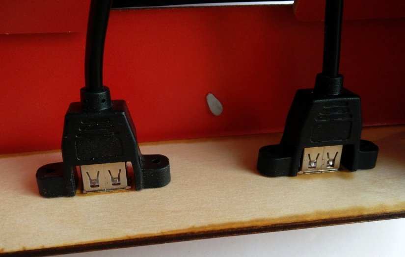
Another sin that needed to be hidden again involved a drill, Dremel and a lack of skill to create cutouts for the front panel USB ports, these needed to be flush and neat, otherwise they would look awful … and they did.
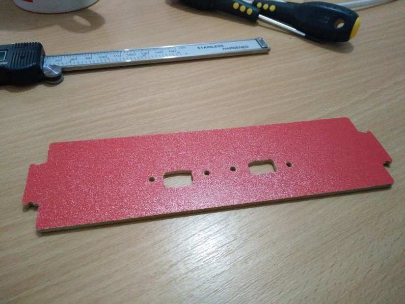
So, when access to the laser cutter was available we made our own ... unique front panel.
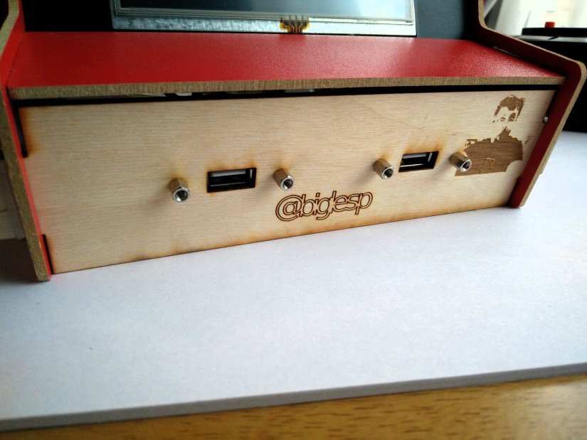
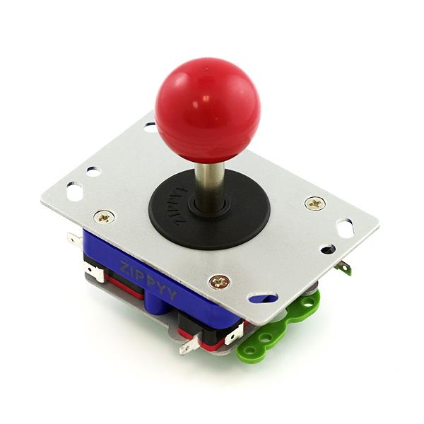
But why did we have these panels? Quite simply because we could not find a joystick and buttons small enough to fit in the 3.5cm x 14cm and the wood was so fragile that it would not take a frantic session of fighting games. This is something to address in our build.
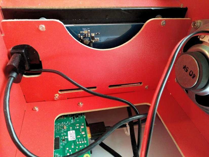
To play audio, we used Pimoroni’s phatbeat board, connected to a 5W 8Ohm speaker. This gave us nice rich sound, and none of the hiss found with the built-in analogue audio of the Raspberry Pi.
The test was successful and I was happily playing Streets of Rage 2 (Classic Megadrive/Genesis title) and Street Fighter 2 thanks to the Retropie emulator.
The test worked, and it gave us ideas to construct our own, so let's take a look at the designs.
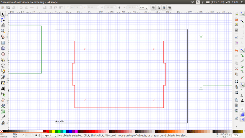
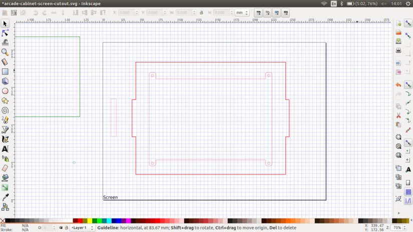
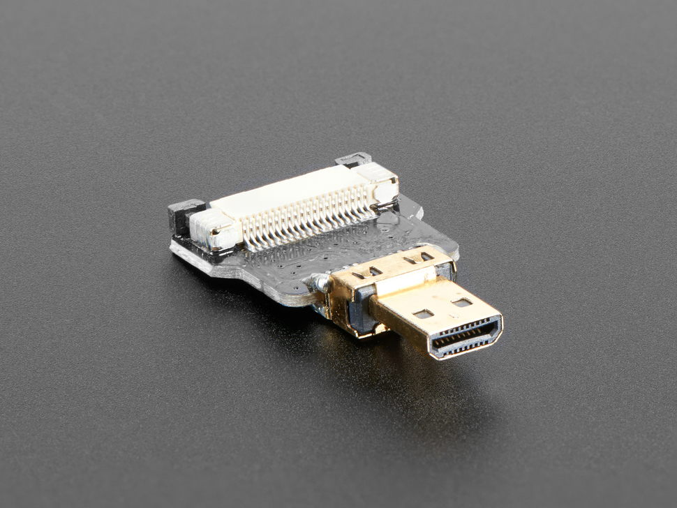
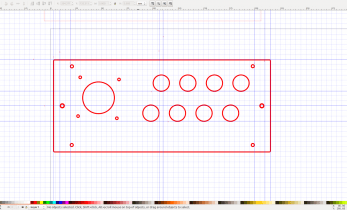
Using Inkscape, we took measurements from the test unit and transferred them to a template. We started with the screen, which has two elements. An acrylic screen protector that fits over the screen and matches the screw holes present on the screen, this means that we can screw through the protector, through the holes in the screen, and into a plywood backing piece. But for this new build we shall be using a much larger screen. This time we have a 7” 1024 x 600 screen, so we need to ensure that any measurements taken are for this screen.
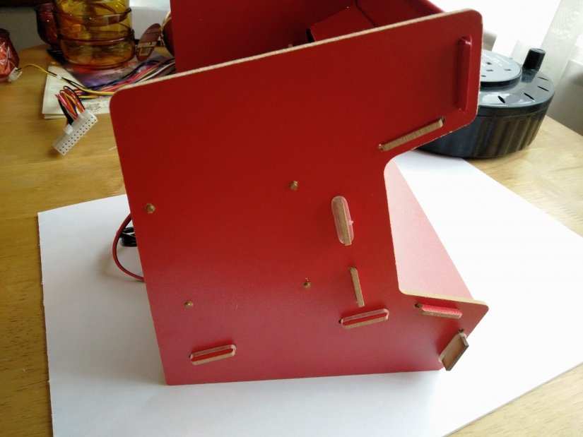
Next, on to the side panels, these will be cut from 6mm plywood as we need the extra strength to support the unit. This will be a tough cut for the K40 as it just has enough power to cut 6mm plywood. Where the screen will be inserted we see a 6mm thick slot, this is for the 3mm acrylic and the 3mm plywood frame.
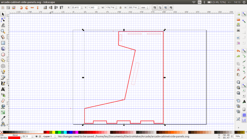
We kept the overall shape simple, no curves etc and we have a depth of 92mm for the controls, plenty of space if we use smaller arcade style buttons. To reinforce the cabinet we added a 6mm thick cross piece to the bottom of the cabinet. This gives us strength and a flat base to ensure stability.
With these basic pieces designed we will take them to the cutter in a couple of weeks and do a test cut on card to see how they look. The design will need to be refined and extra cutouts added for the speaker grills.
So where do we go from here?
This project is much more than “build an arcade cabinet.” It encompasses:
- Taking measurements and applying them to a design for use on the laser
cutter - Sourcing electronics suitable for the build
- Installing the software and hardware to control the cabinet
The project will test our skills as a maker, our patience as we learn from mistakes, and our knowledge of components and the software needed to create the project.
In the next post of this series we shall look at the components and how they will connect together and use their measurements to fine-tune the design of our cabinet.
We will then take our design to the cutter and use the K40 to make our cabinet a reality; then we shall test fit the components and tweak the design accordingly.
In the final post we will connect everything up and tweak our Retropie system to run a selection of classic video games.
DIY Retro Arcade Cabinet - Introduction
DIY Retro Arcade Cabinet - Part 1 - Planning
DIY Retro Arcade Cabinet - Part 2 - Component Selection
DIY Retro Arcade Cabinet - Part 3 - Laser Cutting
DIY Retro Arcade Cabinet - Part 4 - Assembly and Configuration

Les Pounder loves hacking and tinkering with Arduino, Raspberry Pi and new technologies. He passes on his skills and discoveries to Electromaker readers via tutorials and reviews.


Leave your feedback...