
DIY Retro Arcade Cabinet - Part 2 - Component selection
DIY Retro Arcade Cabinet - Introduction
DIY Retro Arcade Cabinet - Part 1 - Planning
DIY Retro Arcade Cabinet - Part 2 - Component Selection
DIY Retro Arcade Cabinet - Part 3 - Laser Cutting
DIY Retro Arcade Cabinet - Part 4 - Assembly and Configuration
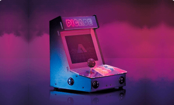
In this second part of the project we look at the components that will be used to build the cabinet, discuss the reason they were chosen, and document their physical dimensions. Why do we do this? Well, we need to plan, test and adapt our design to meet the requirements of the components that we wish to use and it gives us the chance to do a little shopping!
The Controls
So let's start with the most important part of the project and that are the controls. An arcade cabinet needs to have quick controls, provide feedback to the player so that they are confident when fighting off the forces of evil, or eating power pills.
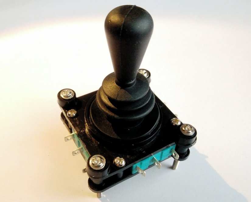
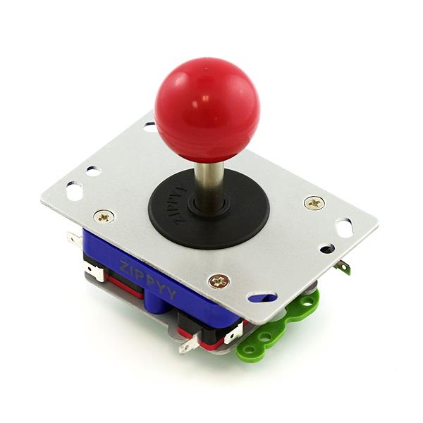
Firstly we have the joystick, typically quite large and made to resist a lifetime of space aliens, 24 hit combos and maybe even Daley Thompson’s Decathlon (known in the 80s for infamously breaking children’s joysticks across the world). The joystick works by suspending a metal shaft inside a spring chamber, when the joystick is moved the metal shaft impacts against a series of micro switches which when connected send a signal to the controller board, which in turn translates the signal into something the game is waiting to react to.
For our cabinet we do not have the space to install a full-size joystick, so we have to get creative. From eBay we found a small joystick that wouldn’t seem out of place controlling a forklift truck. Around the joystick, we can see the micro switch connectors for the outputs. Typically, we have a COM (Common Ground) connection that can be daisy-chained between the micro switches, buttons and other low voltage components.
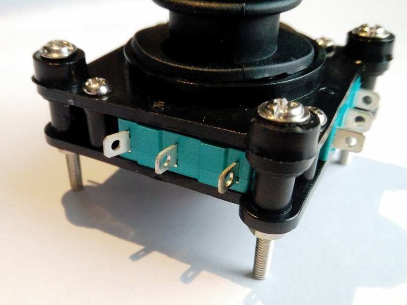
Next, we see connectors marked NO and NC. These are Normally Open, meaning that the circuit is normally broken and when the micro switch is pressed, the circuit is closed. Normally Closed means that the circuit is normally connected and that triggering the micro switch will break the circuit. On the underside of the joystick we can see a restrictor plate, in this case, a four-way restrictor. This is used to restrict the directions that the player can move.
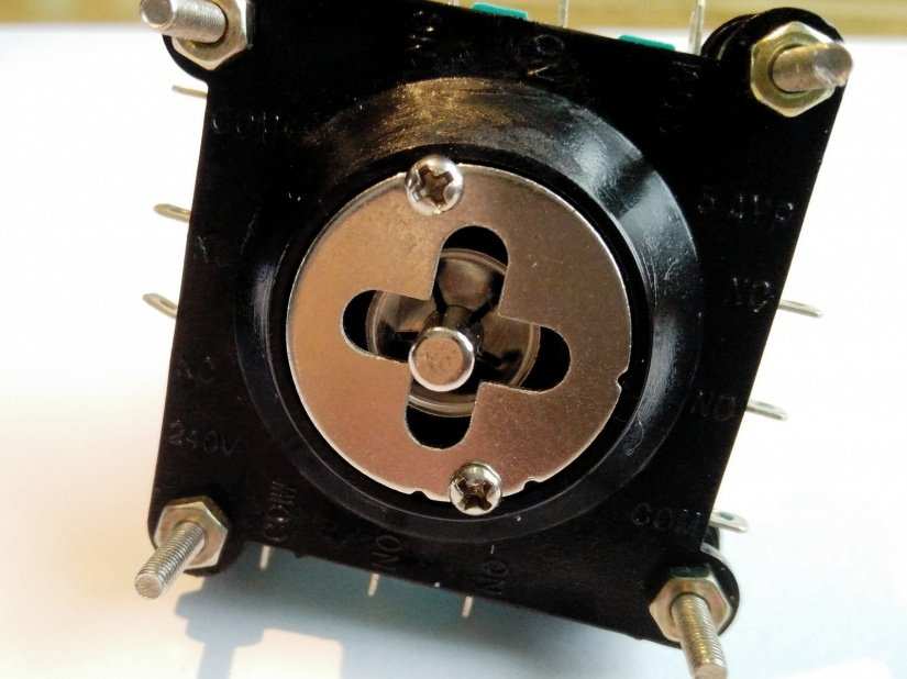
For example Pacman uses a four-way restrictor as there are only four directions in which Pacman can move. There are other types of restrictor plates, typically for restricting movement to only one axis (vertical or horizontal) but the most common restrictor is that used to enable eight-way control, typically used for fighting games such as Mortal Kombat and Street Fighter. For our unit to have the most compatibility we shall remove the restrictor plate completely, thus enabling us to play any type of game.
Joystick dimensions
| Width | 47mm |
| Length | 47mm |
| Height | 67mm |
| Distance from centre of each mounting screw | ~35mm |
| Connectors | 3mm wide |
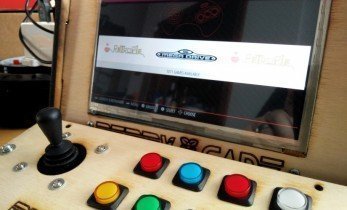
Buttons
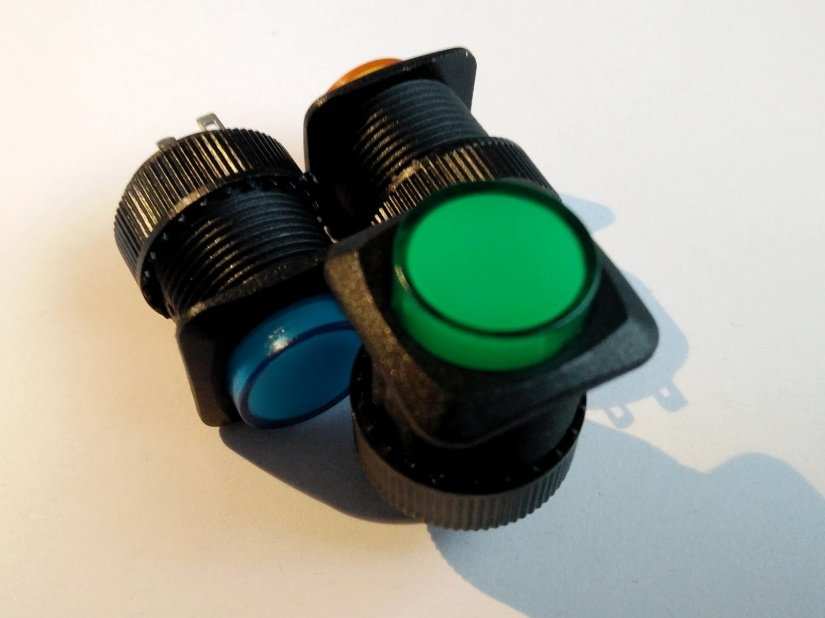
Next, we have buttons, specifically Adafruit’s wonderful 16mm illuminated pushbuttons. This is a normally open pushbutton that makes momentary contact when pushed, it has an audible click, again to give the player feedback. The button also comes with a built in LED (2.2V) which can be easily illuminated from a 3V/5V supply, of course, with a suitable inline resistor to prevent the LED from blowing.
The illumination of the buttons is not strictly necessary, but we are going to do it anyway because LEDs are cool and it will really enhance the project.
Push Buttons details
| Width | 16mm |
| Length | 16mm |
| Height (Button to Connectors) | ~30mm |
| Screw Thread | 15.5mm |
| Connectors | 2mm wide |
![]()
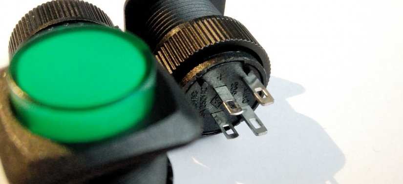
A special button that we happened to pick up from Adafruit was an illuminated power button. This is potentially going to be used with a Pimoroni On/Off Shim to provide a safe way to power up and down the cabinet. Oh, and because it lights up, we will light it up, so we will require an inline resistor to safely power the LED.
| Diameter | 9mm |
| Height | 10mm |
| LED Voltage | 2.2V (Approx) |
The Connections are made!
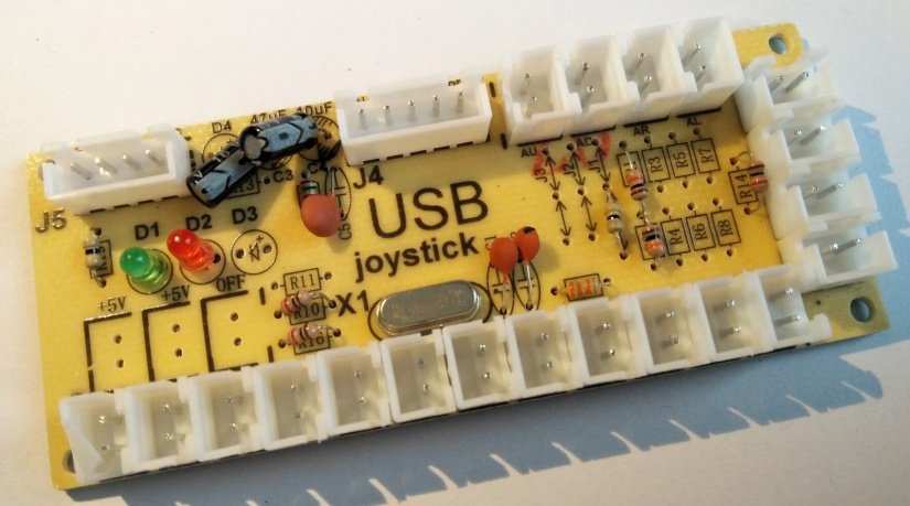
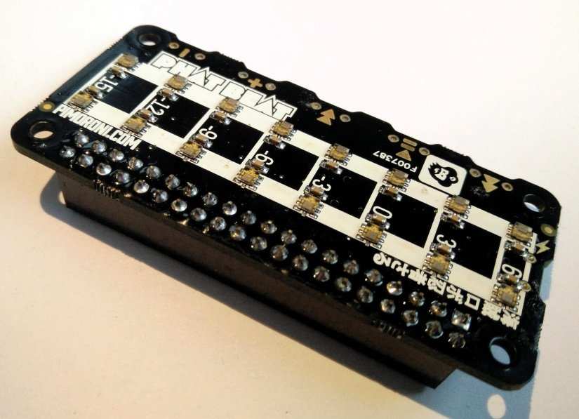
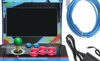
So, where do all of the buttons and our joystick connect to? Direct to the Raspberry Pi GPIO (General Purpose Input Output)? Well no, sure the GPIO is there and we can use it but that will tie up quite a few of the GPIO pins. It means that we cannot attach other devices/components to the Pi. So, instead we are going to use a purpose-built and exceptionally cost-effective board that we picked up from Aliexpress. This board has connections for all of the buttons that we wish to use, but we may need to do a little guesswork to determine what each connection refers to. When connected via USB it will simulate a keyboard interface and send keypresses as we move the joystick or press the FIRE button. This interface can also be created using an Arduino, Teensy or any microcontroller that can emulate a Human Interface Device (HID) but this option requires a little bit of code, and potentially costs more than the chosen option.
Board Dimensions
| Length | 85mm |
| Width | 35mm |
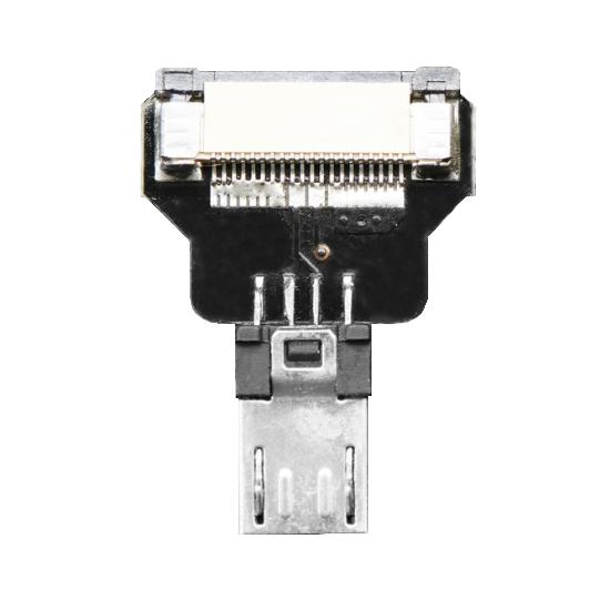
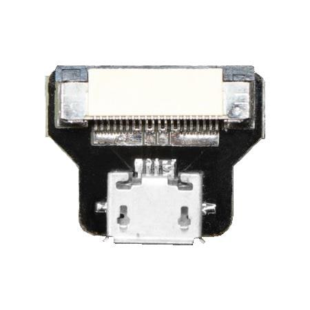
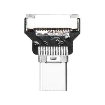
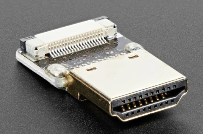
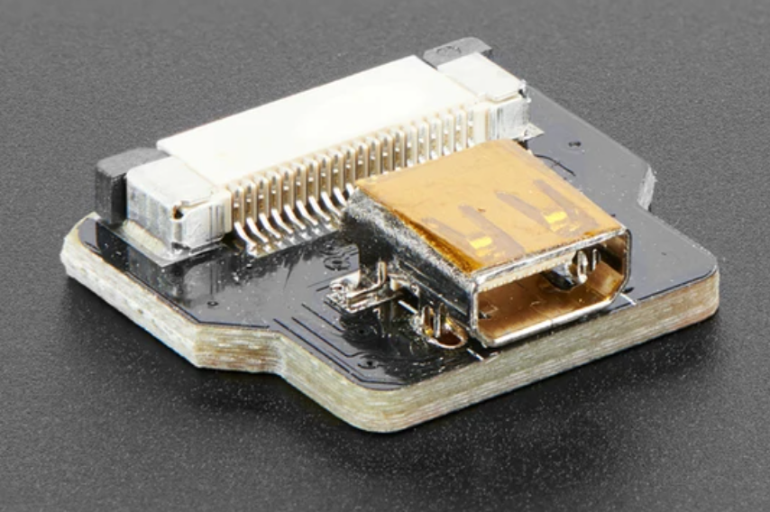
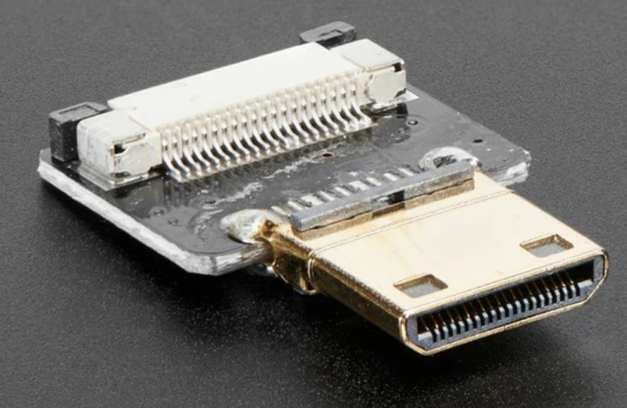
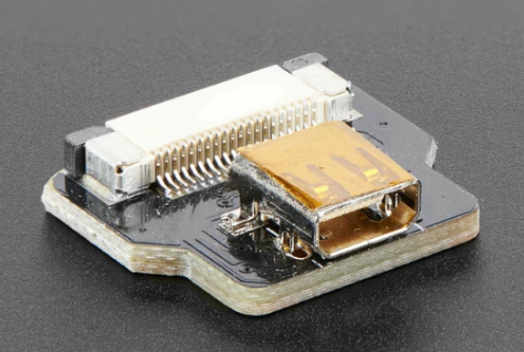
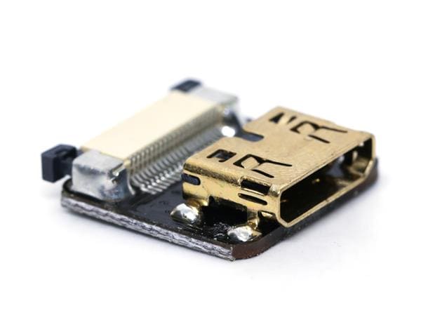
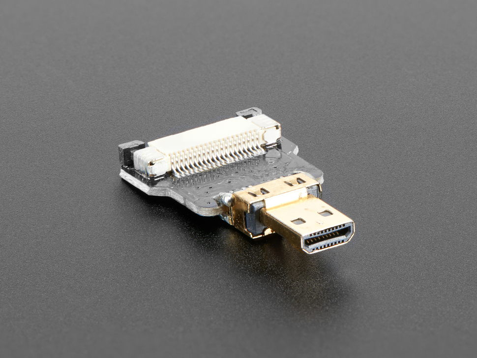
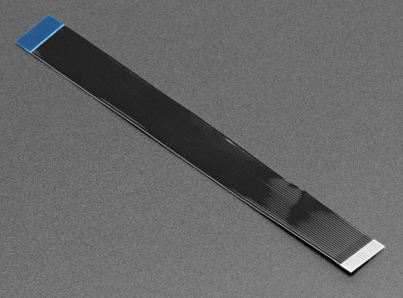
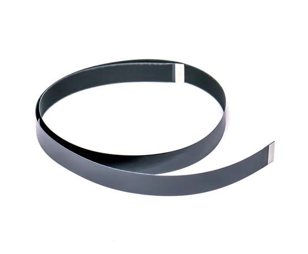
The Screen
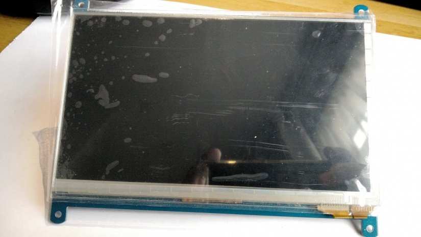
To see our games we need a screen, and for that we have a 7” 1024 x 600 screen purchased from eBay for around $50. This screen uses an HDMI connection, so we can easily connect this to the Pi. Power comes from a 5V micro USB interface which also acts as a touch interface if powered from the USB port of a device.
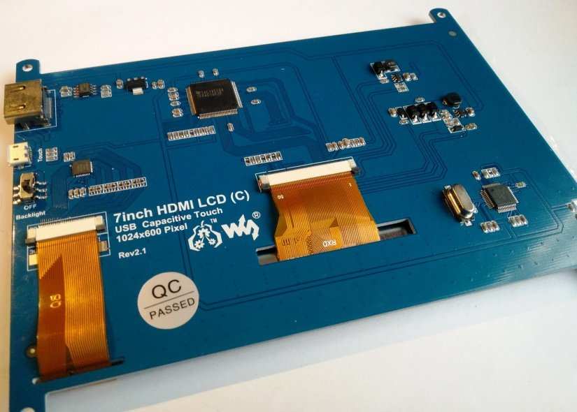
The screen also has four mounting holes that enable the screen to be sandwiched between an acrylic layer and plywood frame to mount the unit in the cabinet.
Screen Dimensions
| Width | 163mm |
| Height | 124mm |
| Depth | 14mm (Thickest Part) |
Audio
So, if we wanted built-in audio, we would use a Pi 3, as we have an analog audio output. But because we want to make a small project, we need to add audio. There are many different options, for example, Pimoroni has their Phat Beat board and in this project we have chosen to use this board, largely based upon its performance in the test unit we constructed.
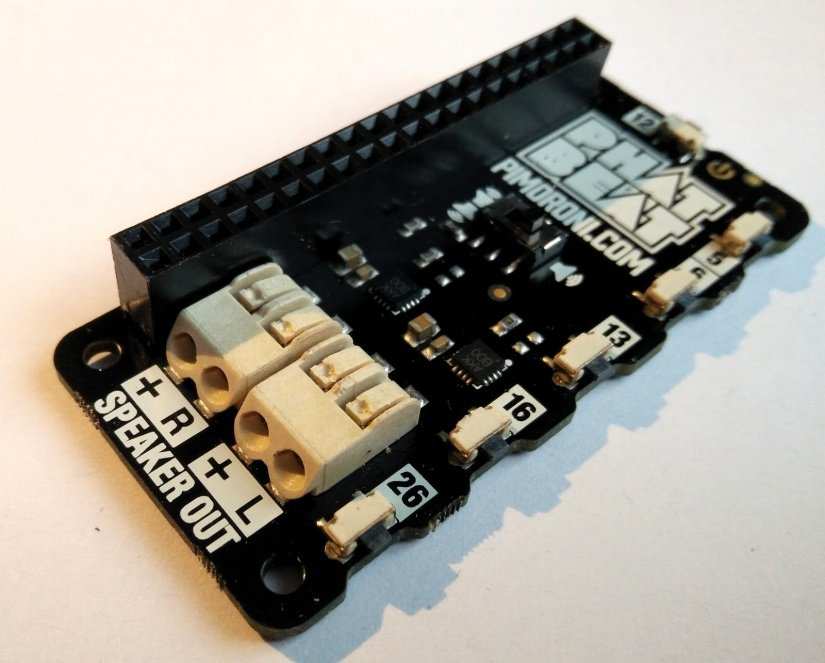
Phat Beat connects to the GPIO of the Pi and uses I2S to output audio via the GPIO. This is then played via an attached 4 Ohm 3W speaker.
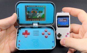
Raspberry Pi Zero W
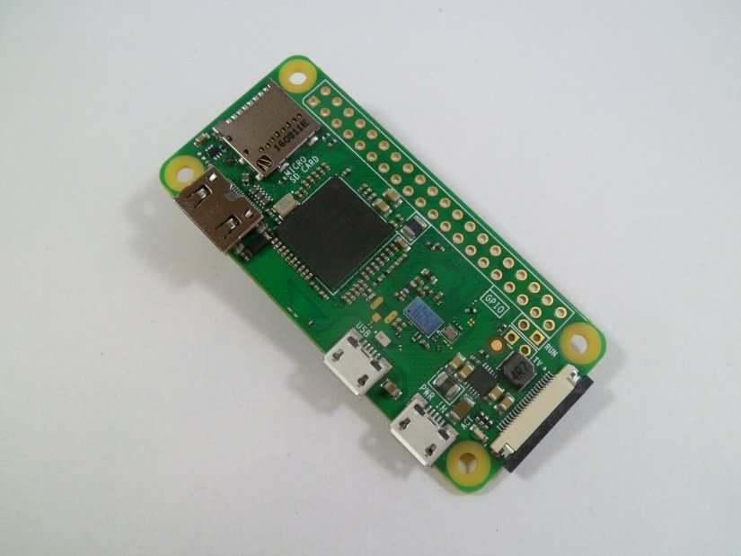
The final piece of the puzzle, the brains of our project, the Raspberry Pi Zero W. Why did we choose this one? Well, it is cheap, around $15-20 and it has WiFi meaning that we can send game files, update the system remotely without the need for plugging in a keyboard and mouse. There is just enough power in the Pi Zero W to emulate up to early 16-bit era, so Genesis / Megadrive, Super Nintendo, era is possible. Earlier arcade games, say up to the late ‘80s are also possible. For anything more recent we would need a board such as Raspberry Pi 3 B + or the ASUS Tinkerboard.
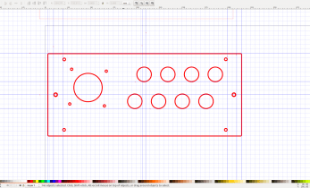
So, we have our kit list, their dimensions and details, next we need to refine the illustrations made in Inkscape to ensure that our cabinet can be correctly cut. Then we can create a test build, check that everything fits, before we fire up the laser to cut into the 6mm plywood and 3mm acrylic we shall use for construction. In the next post we shall be cutting lots of different shapes and testing them out!
See you in part three!
DIY Retro Arcade Cabinet - Introduction
DIY Retro Arcade Cabinet - Part 1 - Planning
DIY Retro Arcade Cabinet - Part 2 - Component Selection
DIY Retro Arcade Cabinet - Part 3 - Laser Cutting
DIY Retro Arcade Cabinet - Part 4 - Assembly and Configuration

Les Pounder loves hacking and tinkering with Arduino, Raspberry Pi and new technologies. He passes on his skills and discoveries to Electromaker readers via tutorials and reviews.


Leave your feedback...