
DIY Retro Arcade Cabinet - Part 3 - Laser Cutting
DIY Retro Arcade Cabinet - Introduction
DIY Retro Arcade Cabinet - Part 1 - Planning
DIY Retro Arcade Cabinet - Part 2 - Component Selection
DIY Retro Arcade Cabinet - Part 3 - Laser Cutting
DIY Retro Arcade Cabinet - Part 4 - Assembly and Configuration
This week we start cutting the cabinet using the K40 laser cutter, and like any complex project, we hit a few issues. But remember dear reader, these issues are not roadblocks, they do not end our journey as a maker, rather they are wrong turns that help us understand how to create complex projects where tolerances are tight.
This part of the project didn’t go exactly to plan. Last Saturday we were due to cut all of the pieces for the cabinet, but we hit a snag or two. So, let's first take a look at the issues we faced and then look at the progress we made. Remember, there is no such thing as failure unless you give up. Learning from failure is an important skill, one that makers soon learn.
Tolerances
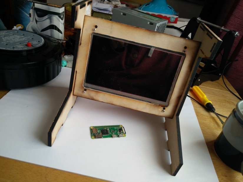
Despite best efforts, our measurements were off, some by around 10mm, others by 1mm. Rather than find this out by wasting plywood, we created some test cuts with card/cardboard and created a test fit. The first piece that was cut, was for the screen, as this ties the two side panels together.
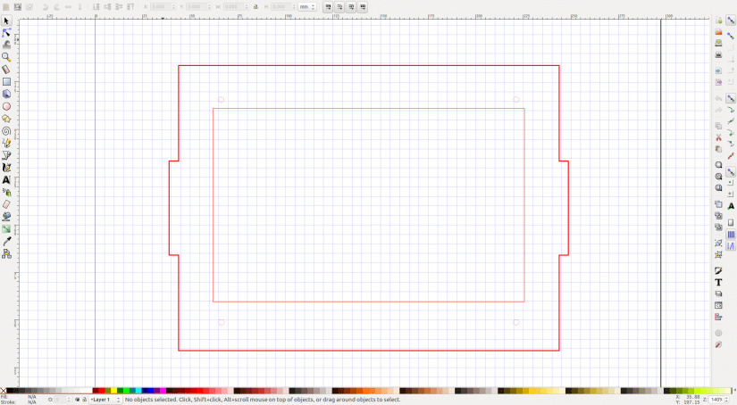
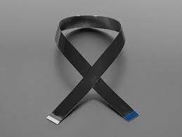
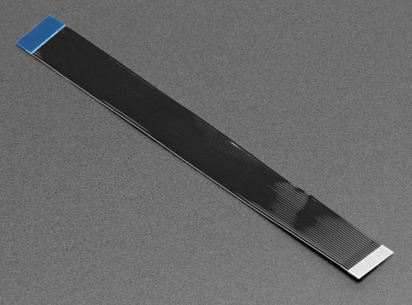
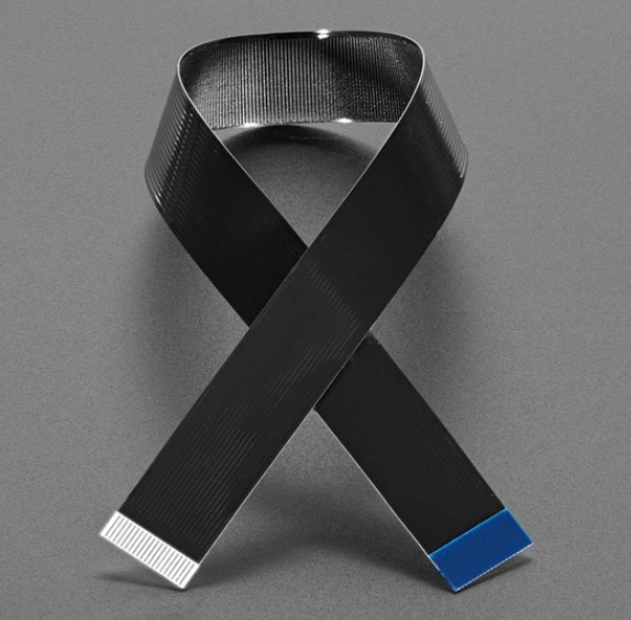
After the first test cut we saw that the screw holes were out by around 8mm and the screen cut out was slightly too small by approximately 2mm. So, off to Inkscape to modify the original files. This is where we hit another problem. The original files combined objects into one larger object, this made sense for cutting, as using object grouping can mean that the vector cut section of the workflow may see multiple passes in one session, which could scorch the material. But by combining the objects we now needed to remove part of the much larger objects. Initially, we used the Node select tool to pick apart the object. But after 30 minutes this became rather unwieldy, so we traced new objects over the old and created a new template for cutting. Taking this over to the cutter and a further test piece was cut, this time we had an almost perfect fit, all that was preventing the screen from being seated correctly was the flat flex cable in one corner. We then cut the final piece and used a rotary multi-tool to gently sand a section of the frame until the screen sat flush. While we had the rotary tool out, we gave the frame a general sanding because we shall be painting the frame later.
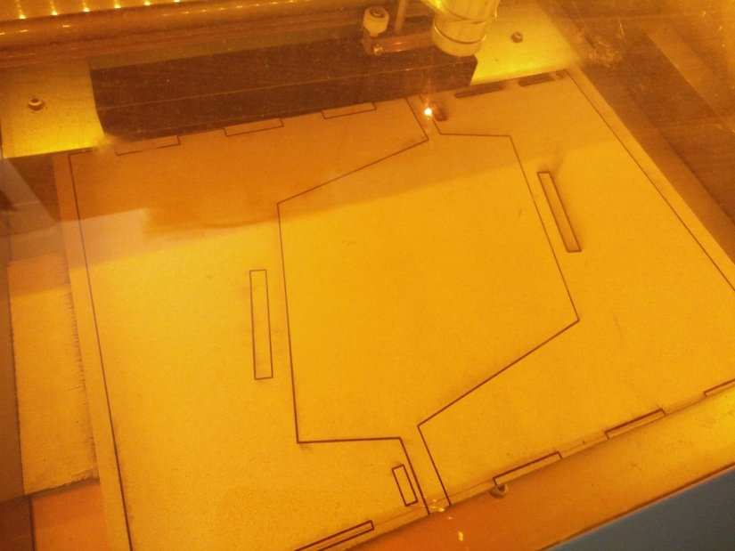
Another tolerance issue that we hit was when we cut the sides of the cabinet. For the sides we used 6mm MDF. Be careful when cutting MDF, the particles that are vaporised are not good for you, so make sure your extraction system is working perfectly before using it, oh and purchase laser grade MDF from reputable stockists. Do not use standard store-bought MDF, get laser grade every time! Now, back to the sides, and when cutting these from a single piece of A4 sized MDF we noticed that despite lining up the material the cut was uneven. After some tinkering with the alignment we found that it was best to cut one side at a time. MDF is slightly easier to cut on the K40, largely thanks to it being of a uniform density and quality. But 6mm MDF is still a challenge for the K40, and we had to turn up the power to around 90% and run the vector cut at 8mm/s to get a cut. But we needed to run the cut multiple times to make sure it went through. In the future, the K40 laser cutter will need an air assist modification to enhance the cutting power of the unit. With the sides cut we inserted the screen frame into the holes cut for it on the cabinet sides, and despite careful measuring, the tabs were too short for the slots cut, by roughly 1.5mm which meant there was a noticeable wobble and not a nice firm friction fit.
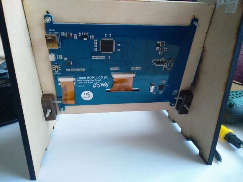
So, instead of cutting a new piece and wasting the plywood we chose to pop to our local hardware store and pick up modular blocks that connect materials at 90-degree angles. These mod blocks are around 10 cents each, so we bought 10 of them just in case.
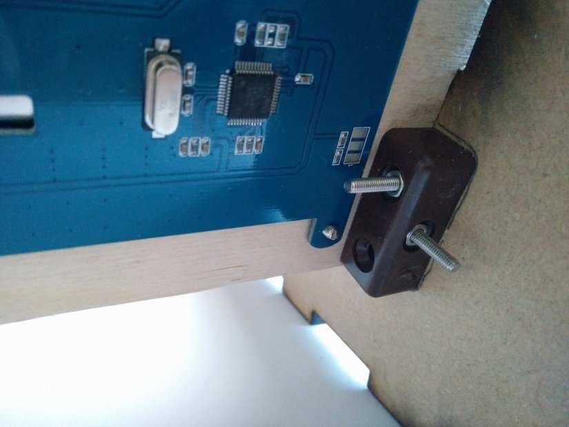
Using the mod blocks to create a firm connection between the screen and the sides was a stroke of genius as now the unit is firm and ready for the screen to be test fitted. Using M3 machine screws and nuts, we secured the screen to the frame and found that the unit looked proportionally correct, and offered a wide enough area for the controls! Now we can design the layout for the controls.
Taking Control
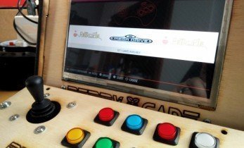
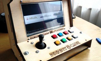
The controls for an arcade cabinet are of vital importance. They are the main way in which we interface with the games we play, so it is crucial that we get it right. Taking careful measurements from the already built cabinet sides and screen we went into Inkscape and created a layout.
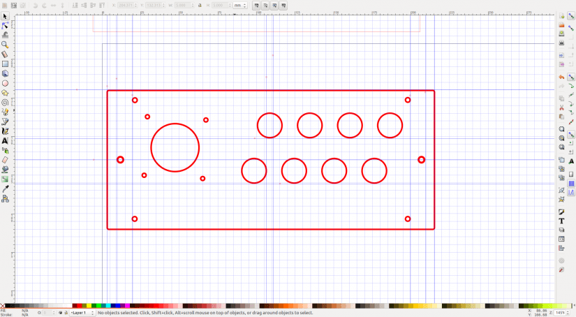
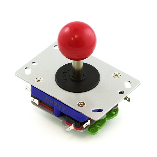
This layout fits over the entire front section of the cabinet, resting the outer edges upon the “slopes” of the cabinet sides. Across the middle line of the layout we see two holes at the outer edge. These are exactly 6mm in from the edge and are used to enable the mod blocks to be screwed and secured to the layout panel, and then to the cabinet sides for a tight fit. In each corner of the panel we can see 3mm screw holes for M3 machine screws that will secure the layout as to protect the underlayer from damage we shall cut a piece of 3mm acrylic using the same template. This enables us to paint/decorate the underlayer, which will be cut from MDF, and protect it with the acrylic. It also means we can etch information on the underlayer and it will not be damaged. For the joystick, we need to cut 3mm holes for it to be secured to the panel, and a larger 32mm hole for the joystick to poke through. This keeps the rubber skirt around the joystick clear of any sharp corners, but we shall use the rotary tool to sand the edges before fitting. To the right we see eight 16mm wide holes for the buttons, these are slightly larger than needed as the K40 cutter has a habit of cutting a little smaller than needed.
These buttons are staggered to give the player plenty of space to accurately hit them, and space between the buttons as they are raised slightly with a plastic collar.
Crowning the cabinet
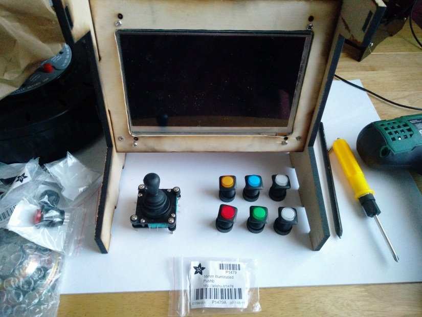
Arcade cabinets have many different ways to attract the player. Demos, loud sounds and flashing signage, typically the marquee just above the screen, are the main way to entice the player to drop a few coins in the slot. Our cabinet will have an acrylic marquee made up of two 3mm layers that will sandwich into the 6mm slots cut into the cabinet sides. The front layer will be a black acrylic, and into that we shall cut the name of the cabinet, Berry Cade. The rear layer will be a piece of neon pink acrylic that will be visible through the cut out sections, causing the marquee to be highly visible and attract players to it.
We have made great progress, a little slower than anticipated but the lessons learned here will help us understand how to replicate the process in the future. Using a laser cutter to prototype projects like this is an iterative process, it is never right the first time, there is always a tweak that we need to make. But this is part of the fun that enables making to be just that … fun!
Next week it will be a mammoth week, as we attach the control panel, wire it up, fit the marquee and the missing panels, attach the Pi Zero, load up some games and test it out. Then we take it apart ready for painting. So, make sure you have plenty of coffee and snacks for the next, and final post in the series.
DIY Retro Arcade Cabinet - Introduction
DIY Retro Arcade Cabinet - Part 1 - Planning
DIY Retro Arcade Cabinet - Part 2 - Component Selection
DIY Retro Arcade Cabinet - Part 3 - Laser Cutting
DIY Retro Arcade Cabinet - Part 4 - Assembly and Configuration

Les Pounder loves hacking and tinkering with Arduino, Raspberry Pi and new technologies. He passes on his skills and discoveries to Electromaker readers via tutorials and reviews.


Leave your feedback...