
DIY Retro Arcade Cabinet - Part 4 - Assembly and configuration
DIY Retro Arcade Cabinet - Introduction
DIY Retro Arcade Cabinet - Part 1 - Planning
DIY Retro Arcade Cabinet - Part 2 - Component Selection
DIY Retro Arcade Cabinet - Part 3 - Laser Cutting
DIY Retro Arcade Cabinet - Part 4 - Assembly and Configuration
Here we are, the end of the journey that has taken us four parts, many mistakes and lots of learning. Building this project has used multiple skills, chiefly design and fabrication using the K40 laser cutter. Using a laser cutter for small projects (keychains, signs etc.) is rather simple, but an arcade cabinet requires careful design and lots of iterations in the fabrication process.
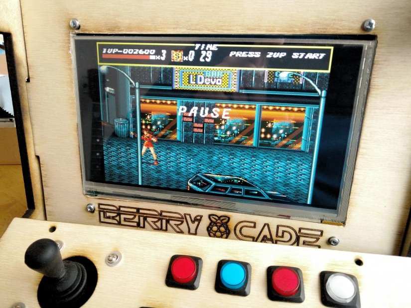
So let's move on and get to the end of this project because Streets of Rage is not going to play itself!
In this final part we shall
- Assemble the cabinet
- Connect the electronics
- Configure Retropie
- Play some games
So, do all the parts fit together?
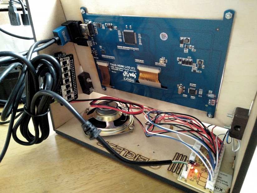
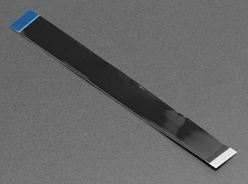
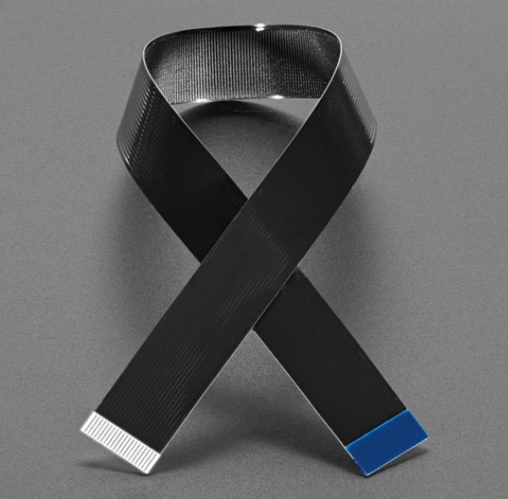
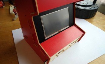
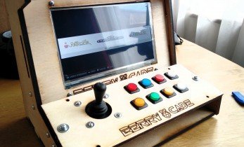
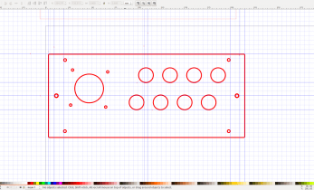
The first step for this final part of the project is to ensure that all of the parts fit snugly. One part that will fit a little too snuggly is the screen. The Makibes 7” screen has an annoying flat flex cable that prevents it sitting flush in the hole cut for it. We will need to use a rotary tool to gently eat into the wood, thinning it out so that the cable is not trapped or damaged. While the pieces should fit nicely, some may need a little filing and sanding before they friction fit into place. The pieces will be firm and hold their place, but after a frantic session on Streets of Rage, they might start to come undone. Next, using modular blocks (mod blocks) from a local hardware store, we inserted the blocks into key areas and used M4 machine screws and nuts to hold the cabinet in place. These key areas are the control panel, and the side panels connecting the screen frame. Mod blocks come in all sorts of shapes and sizes, and your local hardware store can help you find the right ones.
Inserting the buttons
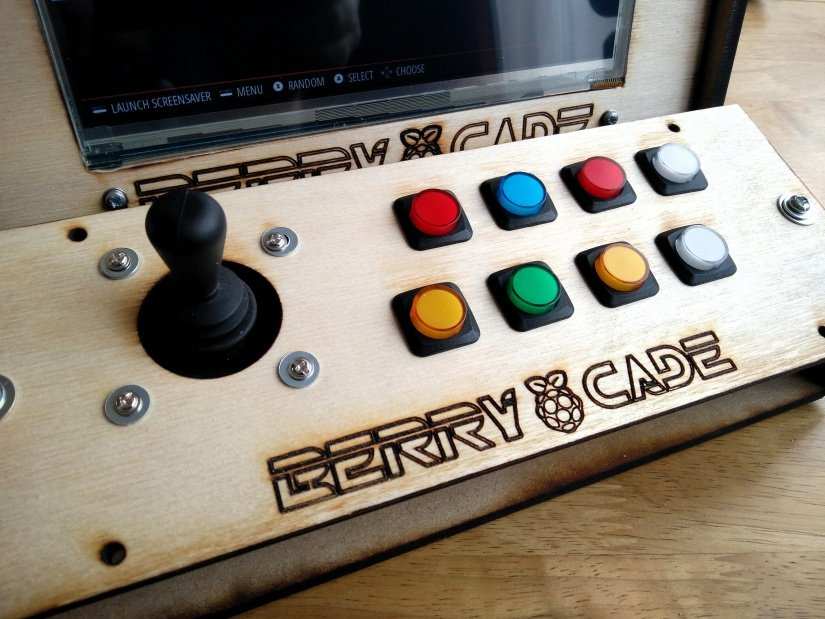
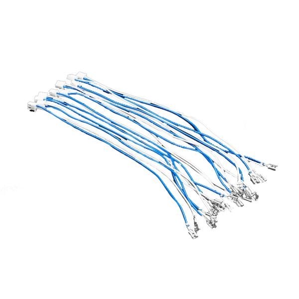
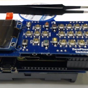
Our buttons have a diameter of 16mm and the holes cut into the control panel have been cut to match that, with just a little extra due to the K40s tolerance issue. The buttons fit neatly and are held in place by a screw cap that holds them to the plywood. How you layout the buttons is entirely up to you, players choose the buttons based on the games that they play. We are quite partial to fighting games so buttons with microswitches, such as these, provide us with an audible click when pressed.
The USB Controller
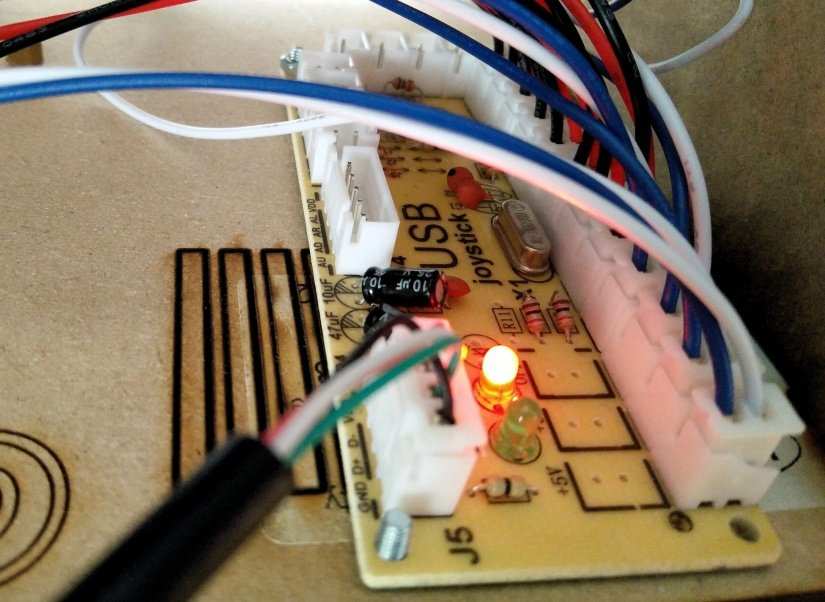
Rather than program our own Arduino solution we used a cost-effective bespoke board. This board converts the button presses and joystick controls of the player into something that the Raspberry Pi can understand. The board comes with plenty of crimped connectors which are used to connect the pins of the buttons to the two pin JST connections present on the board.
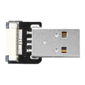
Connecting the buttons to the board is child's play, requiring us to simply press the connections into place. The USB controller then connects to the Pi Zero W via a micro USB adapter which slots inside the USB connection for a neat finish.
The buttons chosen for this project are from Adafruit, and they have four connections present. Two are for button press and another two are marked + and -. These refer to connecting them to a power source to illuminate them, this is an optional step but it would be a most welcome one! The LEDs in the buttons need around 2V to illuminate and this can be supplied from the Raspberry Pi using a suitable resistor.
Phat Beats!
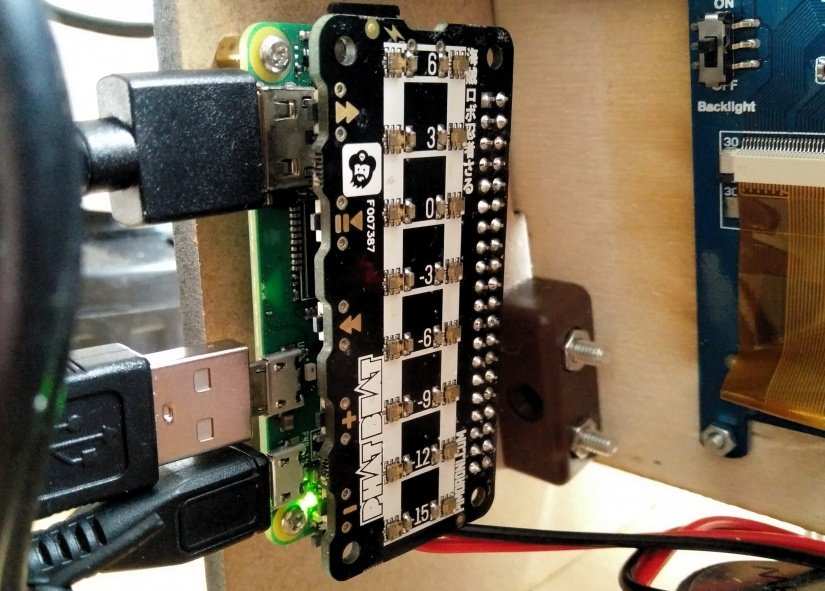
Phat Beat is a powerful sound interface for all models of the Raspberry Pi. Available from Pimoroni, this board fits atop the GPIO and uses the I2S audio interface to send audio over the GPIO. Phat Beat should be inserted on to the GPIO while the Raspberry Pi Zero W is turned off.

Setting Up The Raspberry Pi Zero W
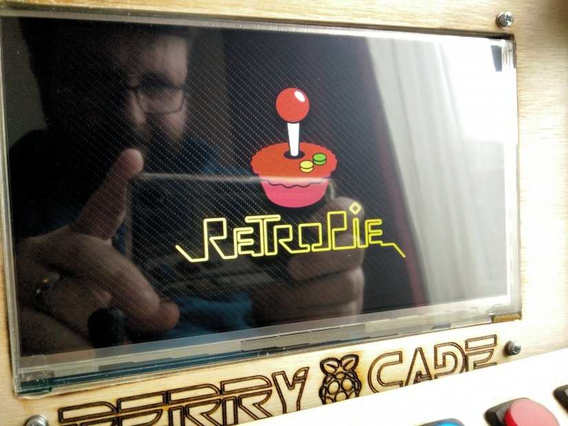
The first software task is to download the Retropie emulation suite and flash it to a micro SD card. The best tool for this job, no matter what operating system you are using, is Etcher. It follows a three-step process. Tell it where the image to flash is, then tell it where you want to flash the image, lastly click on Flash to start.
Once the card has been created we need to enable SSH, a remote login that enables us to configure the Pi Zero W over the network. In the boot partition create a file called ssh to enable SSH logins. Next, we need to set up the onboard WiFi and for this we need to connect up a keyboard, mouse, screen to the Pi Zero W and boot the Retropie software. Once it has booted we will need to complete the button configuration step. For this Retropie will detect the USB controller board we use for the joystick/buttons and then ask us to configure each button. For our eight-button layout we configure the joystick directions, and then the six buttons used for games (punches, kicks, ray guns etc.) and then we configure the START and SELECT buttons. Once completed we are placed into the Emulation Station user interface for Retropie. Now press the START button to open a menu, from there we can select “WiFi” and this will open a new menu. Choose “Connect to WiFi network” then select your home WiFi router name. Then using your keyboard enter your password and press Enter. For a few moments the screen will show “Connecting” before returning you to the first screen, but now your Pi is connected to the WiFi and ready to be controlled using SSH.
Installing the Phat Beat Board
Our Phat Beat board should be attached to the GPIO and our speaker connected. We will need to open the main menu by pressing START and then go to the “QUIT” menu and select “Quit Emulation Station” to return to the standard terminal. Once in a terminal enter the following command to install the Phat Beat software.
curl https://get.pimoroni.com/phatbeat | bash
Follow the installation process until it has completed and then reboot to ensure that the new configuration files are loaded. If you need to adjust the volume use the buttons on the Phat Beat and change to meet your requirements.
Getting our ROMs
Classic video game files are known as ROMs (Read Only Memory) files, largely because cartridge games and arcade cabinets had circuit boards with the games written to chips, ROM chips. This means that the games could be loaded quickly, and reliably. ROM files are dumps of these boards that can be used with emulators.
The problem with ROM files is their dubious legality. While these games may be old and no longer sold, they are still copyrighted and owned by companies/individuals. The general rule of thumb is that you can make copies of your own games, and use those with emulators.
This guide will not tell you where to find ROM files on the Internet, that choice is up to you.
The easiest way to transfer ROMs from your computer to the cabinet is to use a USB flash drive, formatted for Windows. Retropie has an automated tool that enables large numbers of ROMs to be transferred.
- (ensure that your USB is formatted to FAT32)
- first create a folder called retropie on your USB stick
- plug it into the pi and wait for it to finish blinking
- pull the USB out and plug it into a computer
- add the roms to their respective folders (in the retropie/roms folder)
- plug it back into the raspberry pi
- wait for it to finish blinking
- you can now remove the USB stick.
- refresh emulationstation by choosing shutdown from the “Escape” menu and power down the Pi, then reboot.
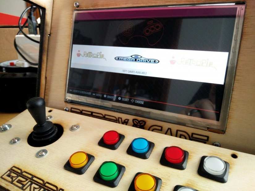
Once the Pi has rebooted the interface will now show the systems for which it has ROMs. In our case we had Megadrive files ready to play so the logo for that console was in the interface. To enter the games for that system we need to press Button 1, which we configured on first boot. You may not remember, or the mapping maybe a little strange but you will find the button soon. Then move down the list and find the game that you wish to play. Press the button and the emulator will start and for a few moments you will see a brief flash of console, advising you on the emulator being used and how you can configure it. This will prove handy if your game doesn’t play, as we can change the emulator and configure each emulator on a per game basis. This will require plenty of trial and error but the results will be worth it.
The End?
So here we are at the end of our journey, and over the weeks we have learnt about fabricating our own arcade cabinet, how to choose the electronics, and how to play the games we loved from our childhood.
This project while it has an exciting outcome, I mean everyone has a favourite game from the past, is more about the process and steps that we took to create the cabinet. We have built our own unique project, no matter what direction you took, you made the choices that dictated the build, you learnt lessons about how to work with the materials, equipment and software that will ultimately change how you work from now own. That is the true goal of this project, playing games is just a bonus.
The total cost of the project is broken down as follows:
| Item | Cost Per Unit | Quantity | Cost |
| Raspberry Pi Zero W | £9.16 | 1 | £9.16 |
| 7” Makibes HDMI screen (1024 * 600) | £48.19 | 1 | £48.19 |
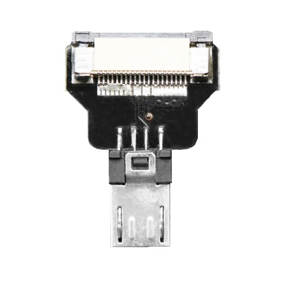
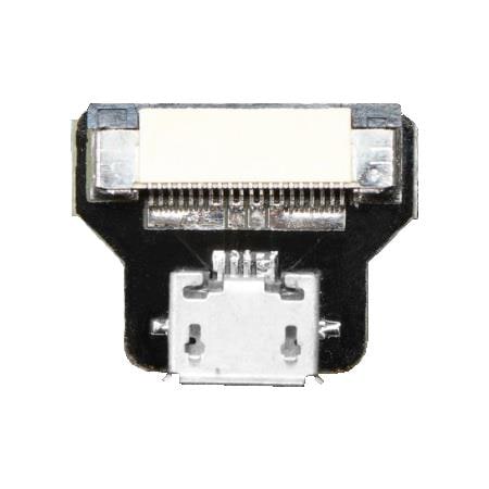
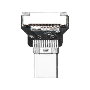
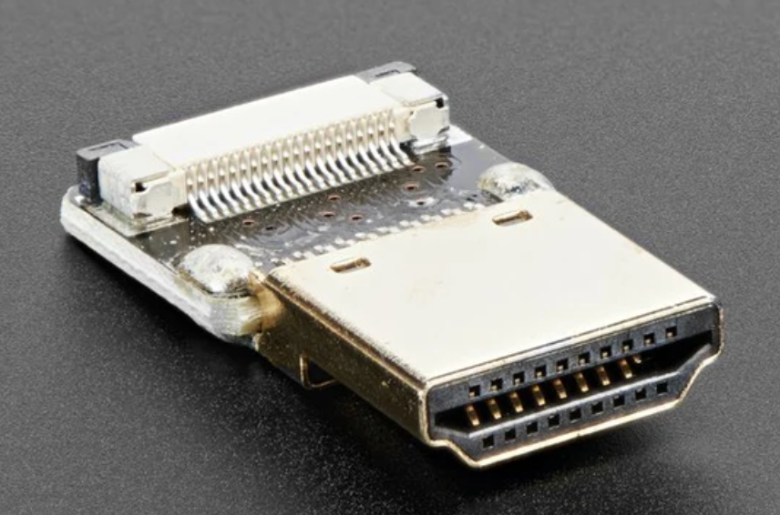
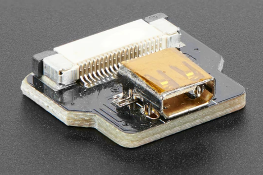
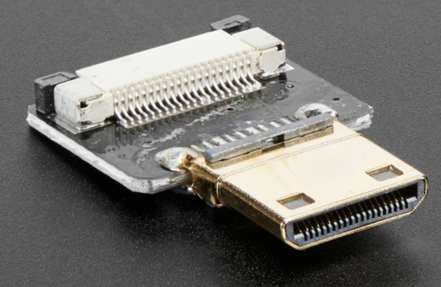
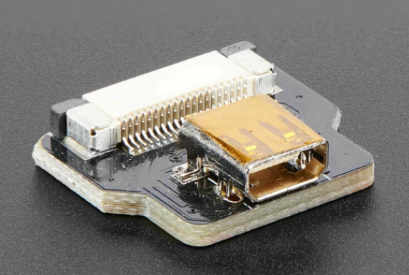
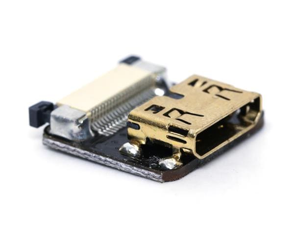
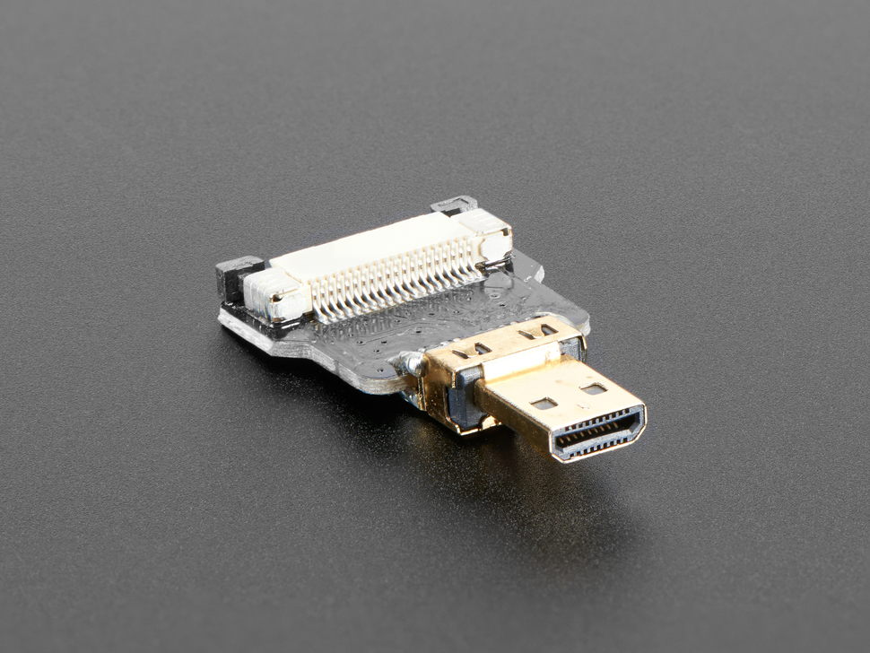
| Right angled HDMI connector | £1 | 1 | £1 |
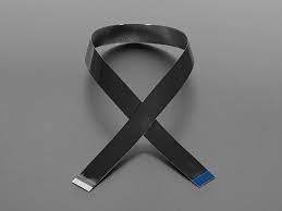
| HDMI to Mini HDMI lead | £5.99 | 1 | £5.99 |
| Phat Beat | £16.50 | 1 | £16.50 |
| Speaker | £2 | 1 | £2 |
| USB control interface | £3.61 | 1 | £3.61 |
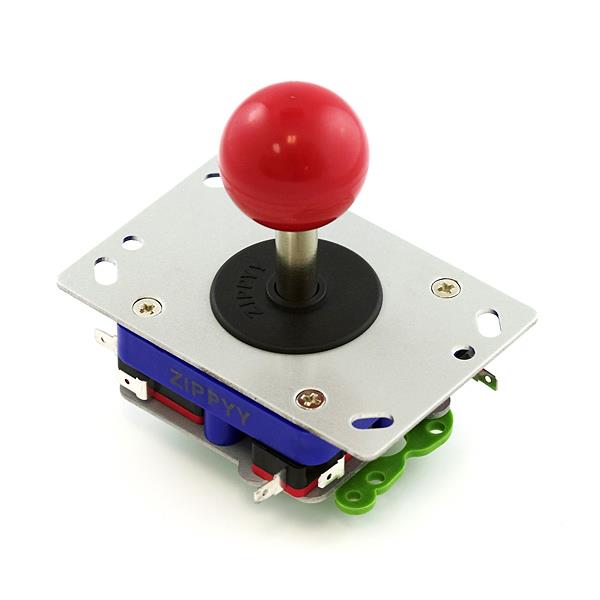
| Joystick | £5.85 | 1 | £5.85 |
| Buttons | £1.50 | 8 | £12 |
| 6mm MDF (A3 Size) | £1.25 | 1 | £1.25 |
| 6mm Plywood (A4 Size) | 35p | 1 | 35p |
| 3mm Pink Acrylic (A4 Size) | £2 | 1 | £2 |
| 3mm Black Acrylic (A4 Size) | £2 | 1 | £2 |
| Modular Blocks | 8p | 10 | 80p |
| M3 machines screws and nuts | Already in bits box | ||
| 2 x USB power supplies (or one with two outputs) | £2 | 1 | £2 |
| Total | £112.70 |
All of the design pieces can be downloaded from our Github repository via this link. It is all provided under a Creative Commons BY 4.0 licence which allows rework, sharing and commercial use, but attribution back to me is required.
So go ahead, build your own cabinets and show them off on Electromaker.io.
DIY Retro Arcade Cabinet - Introduction
DIY Retro Arcade Cabinet - Part 1 - Planning
DIY Retro Arcade Cabinet - Part 2 - Component Selection
DIY Retro Arcade Cabinet - Part 3 - Laser Cutting
DIY Retro Arcade Cabinet - Part 4 - Assembly and Configuration

Les Pounder loves hacking and tinkering with Arduino, Raspberry Pi and new technologies. He passes on his skills and discoveries to Electromaker readers via tutorials and reviews.


Leave your feedback...