
Apply a Filter
Category
- All
- 3D Printing
- Animals
- Art
- Artificial intelligence
- Astronomy
- Augmented Reality
- Automotive
- Bikes
- Clocks
- Communication
- Cryptocurrency
- Displays
- Drones
- Environmental Sensing
- Fire & Pyrotechnics
- Fitness
- Food & Drinks
- Games & Gaming
- Garden
- Health
- Holidays
- Home Automation
- IoT
- Kids & Family
- Lights
- Music
- Notifications
- Photos & Video
- Plants
- Productivity
- Retro Tech
- Robotics
- Security
- Sensors
- Sports
- Star Wars
- Sustainability
- Upcycling
- Vehicles
- Virtual Reality
- Voice
- Wearables
- Weather
Platform
- All
- 4D Systems
- 8bitcade
- Adafruit
- AIY
- AllThingsTalk
- Amazon Alexa
- Amazon Web Services
- Analog Devices
- Android
- Android Things
- Anycubic
- Apple
- Arduino
- Arm
- Arm Mbed
- Atlas Scientific
- Atmel
- Autodesk
- Avnet
- balena
- Bare Conductive
- BeagleBoard
- BITalino
- Blues Wireless
- Bluz
- Blynk
- Bolt IoT
- Bosch
- C.H.I.P
- circuito.io
- CircuitPython
- Commodore 8-bit
- ControlEverything.com
- Creator
- Cypress
- DeviceHub.net
- Dexter Industries
- DFRobot
- Digilent
- Digispark
- Eclipse IoT
- Edge Impulse
- EduBlocks
- Elecrow
- Electric Imp
- Elegoo
- Elephant Robotics
- Ender
- Espressif
- Espruino
- Everything ESP
- evive
- Firmware Modules
- GoPro
- HARDWARIO
- Helium
- Hologram
- Home Assistant
- Honeywell
- IBM
- ICStation
- Idiotware Shield
- IDT
- IFTTT
- Infineon
- Intel
- Itead
- Java
- JLCPCB
- Jupyter
- KiCad
- LabVIEW
- LattePanda
- Leap Motion
- LEGO MindStorms
- LeMaker
- Linux
- Linux Arm
- Losant
- M5Stack
- Mac
- Makeblock
- Makestro
- MATLAB
- MATRIX Labs
- Maxim Integrated
- Meadow
- MediaTek Labs
- micro:bit
- Microchip
- MicroPython
- Microsoft
- MikroE
- MikroElektronika
- MIT App Inventor
- Mouser
- MQTT
- myDevices
- nanoFramework
- NeoPixel
- Netduino
- Neuton Tiny ML
- noads
- Node-RED
- NodeMCU
- Nordic Semiconductor
- NVIDIA
- NVIDIA Jetson
- NXP
- Oculus
- ON Semiconductor
- Onion Corporation
- OpenCat
- OpenCV
- OSH Park
- Panasonic
- Particle
- PCBWay
- Philips hue
- PHPoC
- Pi Supply
- Pimoroni
- PINE64
- PlatformIO
- Prusa
- Punch Through
- PX4
- Pycom
- Python
- Qualcomm
- RakWireless
- Raspberry Pi
- Red Pitaya
- RedBear
- Relayr
- Renesas
- RISC-V
- RobotGeek
- ROS
- RT-Thread
- Samsung IoT
- Seeed Studio
- SensiML
- Siemens
- Sigfox
- Silicon Labs
- SmartMatrix
- SmartThings
- Soldered Electronics
- Sony
- SparkFun
- STM32 Nucleo
- STMicroelectronics
- Taoglas
- Teensy
- TensorFlow
- Texas Instruments
- The Tactigon
- The Things Network
- Thinger.io
- Things On Edge
- thingSoC
- ThingSpeak
- TI LaunchPad
- TinyCircuits
- Tuya
- Twilio
- Ubidots
- Ubuntu
- UDOO
- Unity
- Visuino
- VoCore
- Walabot
- Weather Underground
- Wilderness Labs
- Windows
- WIZnet
- Xamarin
- XBee
- Xilinx
- Zerynth
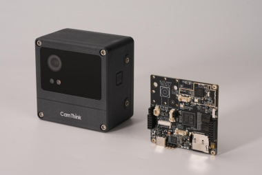
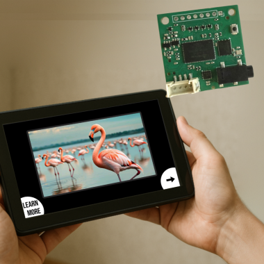
Camthink Neoeyes Ne301 End-to-end Edge-ai Toolkit
AI Tool Stack is an end-to-end edge-AI toolkit for NeoEyes NE301 (and similar) devices, covering data collection, labeling, training, quantization, and deployment. It can be self-hosted and continuously updated.
By
dave-chris
Moderate
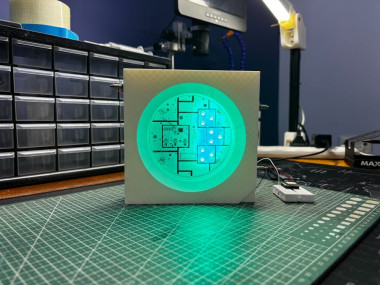
Neopixel Giant Edition
Made an XL version of the beloved WS2812B addressable LED that works like its original counterpart!
By
arnov-sharma
Easy
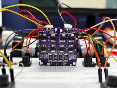
Motor Driver Patch
Motor Driver Patch is a DIY H-bridge-based dual motor driver featuring 8 N-channel MOSFET ICs connected in an H-bridge configuration.
By
arnov-sharma
Easy
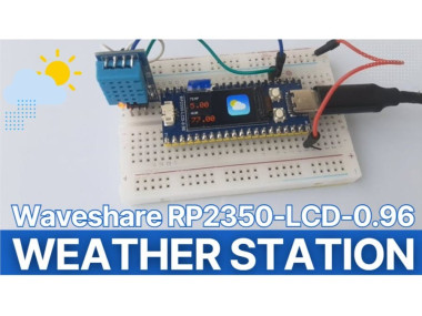
Rp2350-lcd Weather Station With Color Warning Alerts
Create a simple and beginner-friendly weather station using the Waveshare RP2350-LCD 📟 and DHT11 🌡️ sensor in Visuino.
By
Ron
Easy

Make Your Own 3d Printed Diwali Diyas At Home
In this tutorial, I will show you guys how I created these super simple 3D printed Diwali Diyas
By
tarantula3
Easy
Forest Guard
Forest Guard: A Decentralized Edge-AI LoRa Mesh Network for Forest Surveillance
Difficult
Build A Talking Quiz About Animals
A reusable template for makers: touch UI, instant reaction, and MCU-based neural speech.
CrowPanel UI + TinyTTS voice: instant offline speec
By
Grovety
Easy
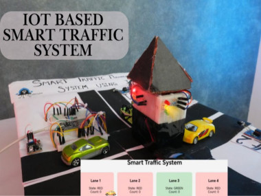
Smart Traffic Management System Using Iot With Esp32
Reduce Urban Congestion by 35-45% with Intelligent, Adaptive Traffic Control.
Easy
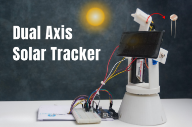
Arduino Dual-axis Solar Tracker: 40% More Power
Arduino-powered dual-axis solar tracking system using LDR sensors and servo motors boosts solar panel efficiency by up to 40% over a fixed.
Moderate
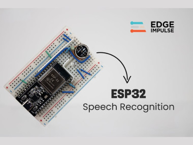
Offline Esp32 Voice Recognition With Edge Impulse
Build a fully offline ESP32 voice assistant using Edge Impulse and an I²S mic. Runs local ML inference for fast, private voice commands.
Moderate
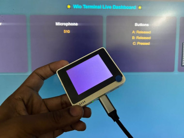
Building A Live Web Dashboard On Wio Terminal
You’ve built a self‑contained IoT dashboard that makes the Wio Terminal interactive and visually engaging over Wi‑Fi.
By
CETECH11
Easy
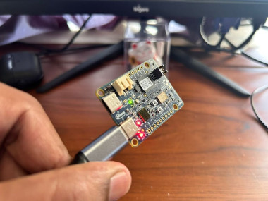
Getting Started With Psoc™ 6 Ai Kit On Arduino Ide
Will guide you to use the PSOC 6 AI kit with Arduino IDE and Web Server.
By
CETECH11
Easy
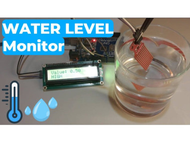
Arduino Water Level Display – Real-time Level On I2c Lcd
In this Visuino project, you’ll learn how to easily measure and display water levels using a water level sensor and an I2C LCD
By
Ron
Easy
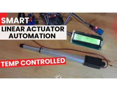
Set Temperature Actuator Responds Arduino Using Lcd
In this Visuino project, you will learn how to control a linear actuator automatically based on temperature.
By
Ron
Easy

World's First Evil Talking Labubu
Labubus have invaded every sidewalk we can think of. So much so that it started dragging around its own urban legend : Labubus are reincarnation of the mezopotamian god Pazuzu. So I tried to see what that would actually look like with a bit of engineering.
Easy
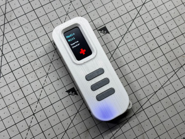
Medic Mini
Medic Mini is a handheld ESP32-C6 device that checks symptoms using simple button inputs.
By
arnov-sharma
Easy
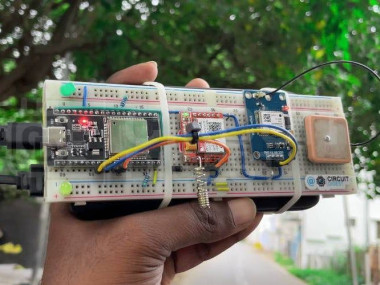
Esp32-based Gps Tracker Using Sim800l And Neo-6m
We build a GPS tracker using the ESP32, SIM800L GSM module, and the NEO-6M GPS receiver, and connect it all to a free cloud dashboard.
Moderate
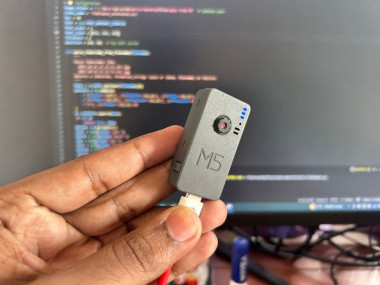
Diy Timelapse Camera With M5stack Timercamera X
Will guide you to build a simple TimeLapse Camera with TimerCamera X
By
CETECH11
Easy