
Led Matrix Countdown Timer Using Visuino

Made by Ron / Clocks / Displays / Notifications / Security
About the project
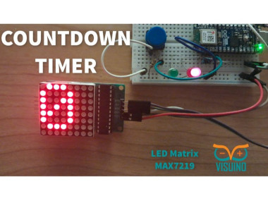
In this tutorial we are going to build a simple Countdown timer using LED Matrix MAX7219 and Arduino. Watch the Video!
Project info
Difficulty: Easy
Platforms: Arduino, DFRobot, Maxim Integrated, Seeed Studio, Visuino
Estimated time: 1 hour
License: GNU General Public License, version 3 or later (GPL3+)
Items used in this project
Hardware components

Story
By pressing on the button you can the Green LED will glow and the timer will countdown from 9 yo 0, once the 0 is reached a Red LED will glow. You can replace the LED with a relay or any other module.
Step 1: What You Will Need1 / 8
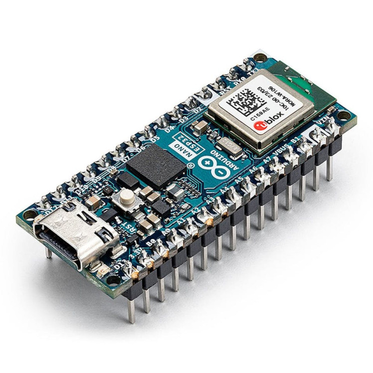

- Arduino (or any other board)
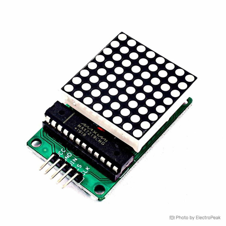
- 8X8 LED Matrix MAX7219
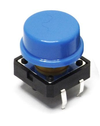
- Button
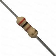
- 3X 1K ohm resistor
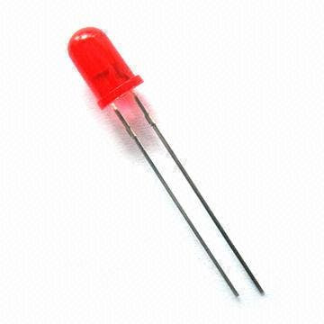
- Green LED
- Red LED
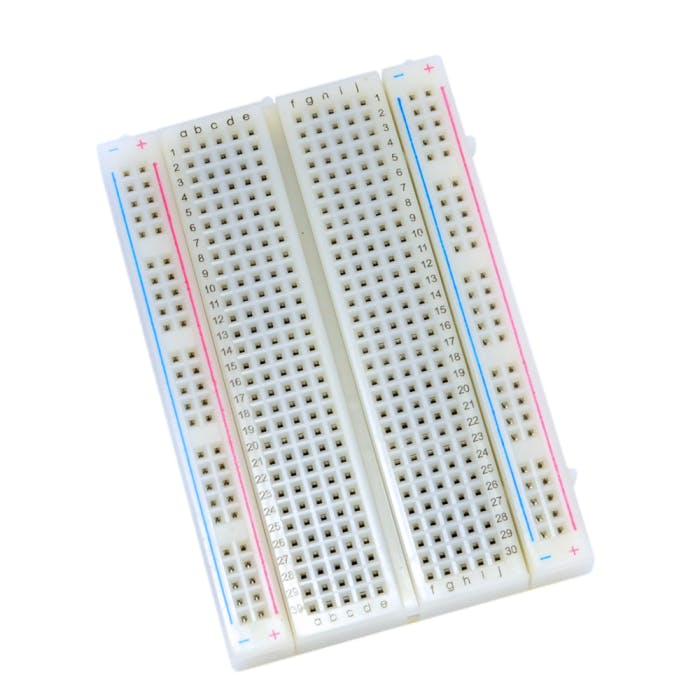
- Breadboard
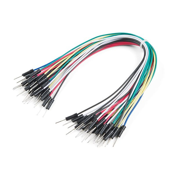
- Jumper wires
- Visuino program: Download Visuino
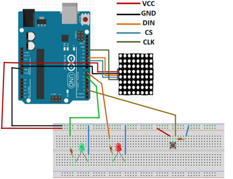
- Connect Arduino pin [5V] to breadboard positive pin [Red line]
- Connect Arduino pin [GND] to breadboard negative pin [Black line]
- Connect Arduino Digital pin [7] to the Resistor2
- Connect other side of the resistor2 to the Red LED positive pin
- Connect Red LED negative pin to breadboard pin [GND]
- Connect Arduino Digital pin [6] to the Resistor1
- Connect other side of the resistor1 to the Red LED positive pin
- Connect Red LED negative pin to breadboard pin [GND]
- Connect Arduino Digital pin [2] to button on the breadboard and to the Resistor3
- Connect other side of the resistor3 to the breadboard pin [GND]
- Connect Other pin of the button to the breadboard positive pin [5V]
- Connect LED Matrix pin[VCC] to Arduino pin[5V]
- Connect LED Matrix pin[GND] to Arduino pin[GND]
- Connect LED Matrix pin[DIN] to Arduino digital pin[11]
- Connect LED Matrix pin[CS] to Arduino digital pin[10]
- Connect LED Matrix pin[CLK] to Arduino digital pin[13]
1 / 2
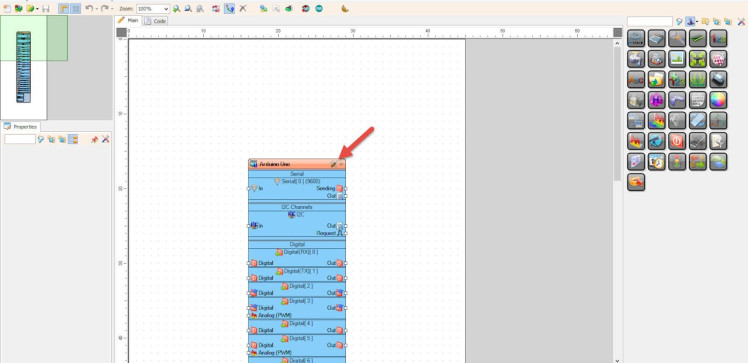
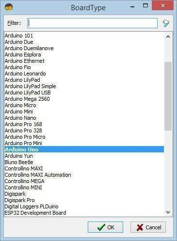
Start Visuino as shown in the first picture Click on the "Tools" button on the Arduino component (Picture 1) in Visuino When the dialog appears, select "Arduino UNO" as shown on Picture 2 or any other board.
Step 4: In Visuino Add Components1 / 8
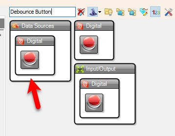
- Add "Debounce Button" component
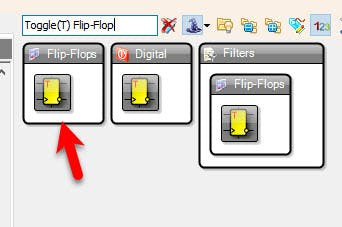
- Add "Toggle(T) Flip-Flop" component
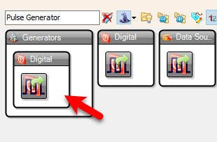
- Add "Pulse Generator" component
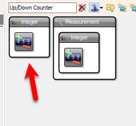
- Add "Up/Down Counter" component
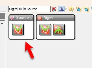
- Add "Digital Multi Source" component
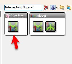
- Add "Integer Multi Source" component
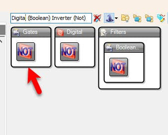
- Add "Digital (Boolean) Inverter (Not)" component
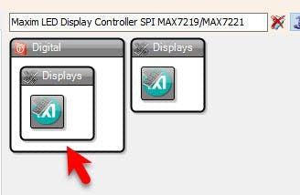
- Add "Maxim LED Display Controller SPI MAX7219/MAX7221" component
1 / 7


Select "PulseGenerator1" and in the properties window select "Enabled" and set it to False, click on the pin icon and select "Boolean SinkPin"
Select "UpDownCounter1" and in the properties window set:
- Initial Value to 9
- Max > Roll Over to False
- Max > Value to 9
- Min > Roll Over to False
- Min > Value to 9
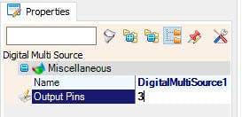
Select "DigitalMultiSource1" and in the properties window set "Output Pins" to 3
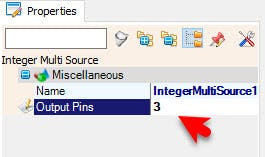
Select "IntegerMultiSource1" and in the properties window set "Output Pins" to 3
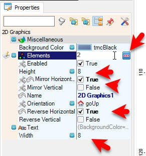
- Double click on the "LedController1" and in the "Pixel Groups" window drag "2D Graphics" to the left side
- and in the properties window set "Mirror Horizontal" to True and "Reverse Horizontal" to True and set "Width" to 8 and "Height" to 8
- also select "Elements" in the properties window and click on the 3 dots button
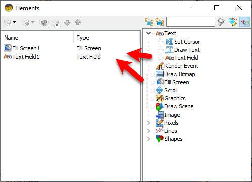
In the Elements window drag:
- "Fill Screen" to the left side
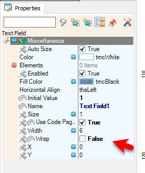
- "Text Field" to the left side and in the properties window set "Wrap" to False
- Close the "Elements" Window
- Close the "Pixel Groups" window
1 / 4
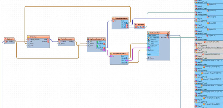
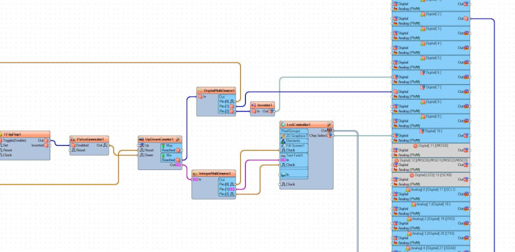

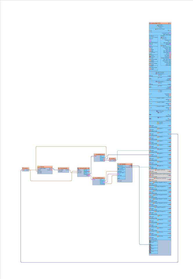
- Connect Arduino digital pin [2] to "Button1" pin [In]
- Connect "Button1" pin [Out] to "TFlipFlop1" pin [Clock]
- Connect "Button1" pin [Out] to "UpDownCounter1" pin [Reset]
- Connect "TFlipFlop1 pin [Out] to "PulseGenerator1"digital pin [Enabled]
- Connect "PulseGenerator1" pin [Out] to "UpDownCounter1" pin [Down]
- Connect "UpDownCounter1" pin [Min Reached] to "DigitalMultiSource1" pin [In]
- Connect "UpDownCounter1" pin [Out] to "IntegerMultiSource1" pin [In]
- Connect "DigitalMultiSource1" pin [0] to "TFlipFlop1" pin [Reset]
- Connect "DigitalMultiSource1" pin [1] to Arduino digital pin [7]
- Connect "DigitalMultiSource1" pin [2] to "Inverter1" pin [In]
- Connect "Inverter1" pin [Out] to Arduino digital pin [6]
- Connect "IntegerMultiSource1" pin [0] to "LedController1" > "Fill Screen1" pin [Clock]
- Connect "IntegerMultiSource1" pin [1] to "LedController1" > "Text Field1" pin [In]
- Connect "IntegerMultiSource1" pin [1] to "LedController1" > "Text Field1" pin [Clock]
- Connect "LedController1" Pin Out SPI to Arduino Board pin SPI In
- Connect "LedController1" Pin Chip Select to Arduino Board Digital pin [10]
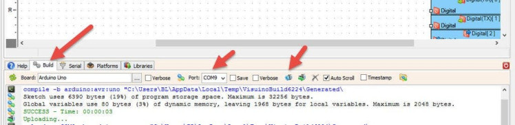
In Visuino, at the bottom click on the "Build" Tab, make sure the correct port is selected, then click on the "Compile/Build and Upload" button.
Step 8: PlayIf you power the Arduino board, the LED Matrix will show the countdown time, if you press the button you will be able to reset the time. When the countdown is active a Green LED will glow, once the countdown is finished a Red LED will glow.
Congratulations! You have completed your project with Visuino. Also attached is the Visuino project, that I created for this tutorial, you can download it and open it in Visuino: https://www.visuino.eu
Schematics, diagrams and documents
Code
Credits
Related products


Leave your feedback...