
Led Indicator Module Light Effects Using Visuino

Made by Ron / Displays / Environmental Sensing / Lights / Sensors
About the project
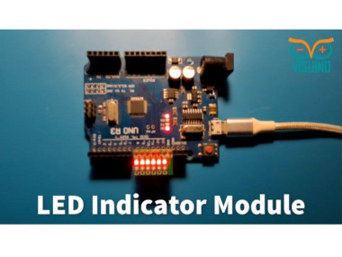
In this tutorial we will learn how to use LED Indicator Module using Visuino. Watch the video!
Project info
Difficulty: Easy
Estimated time: 1 hour
License: GNU General Public License, version 3 or later (GPL3+)
Items used in this project

Story
This module is very useful when you need to indicate some status from sensors or other modules.
Step 1: What You Will Need1 / 3
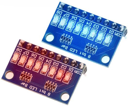
Here we are using a module with 6 LEDs, if you will use a module with more LEDs you might need to connect it to other digital pins or use a breadboard
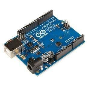
- Arduino UNO or Arduino Mega
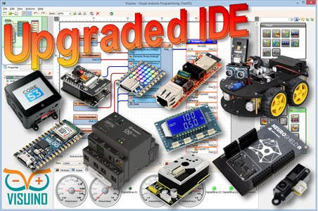
- Visuino program: Download Visuino
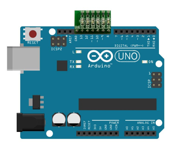
For module with 6 LEDs: Put the module on the Arduino board digital pins [8, 9, 10, 11, 12, 13, GND]
- D6 > digital pin [8]
- D5 > digital pin [9]
- D4 > digital pin [10]
- D3 > digital pin [11]
- D2 > digital pin [12]
- D1 > digital pin [13]
- GND > pin [GND]
If you are using a module with more LEDs you might need to use other digital pins or connect it to the breadboard.
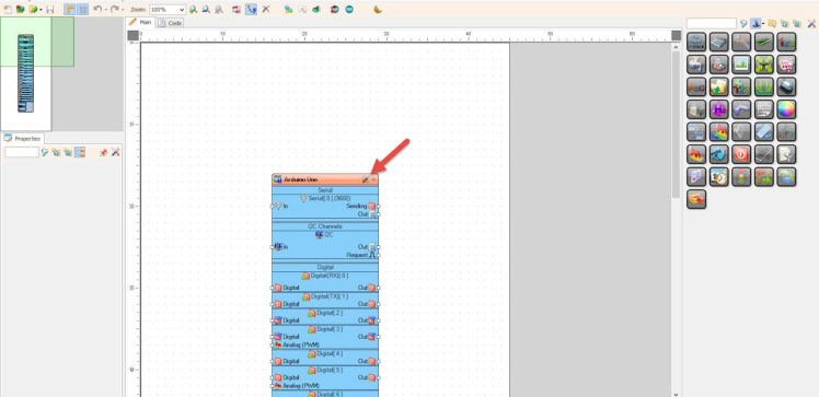
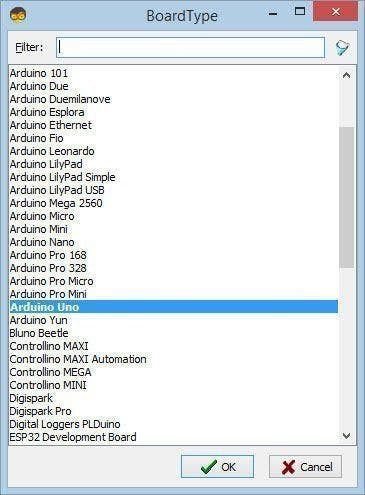
Step 3: Start Visuino, and Select the Arduino UNO Board Type1 / 2


Start Visuino as shown in the first picture Click on the "Tools" button on the Arduino component (Picture 1) in Visuino When the dialog appears, select "Arduino UNO" as shown on Picture 2
Step 4: In Visuino Add & Set Components1 / 6
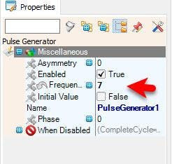
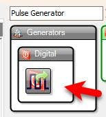
- Add "Pulse Generator" component
- To set the speed of the LEDs, set the "Frequency" in the properties to 7 or any other value you might like
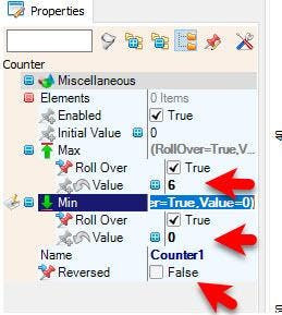
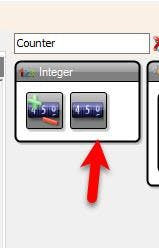
- Add "Counter" component, and in the properties window set "Max" > "Value" to 6 <<Number of LEDs on the module and "Min" > "Value" to 0
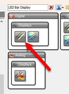
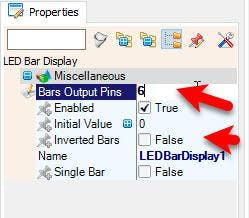
- Add "LED Bar Display" component and in the properties window set "Bars Output Pins" to 6 <<Number of LEDs on the module
To change the LED direction select "Counter1" and in the properties window set "Reversed" to True
or select "LEDBarDisplay1" and in the properties window set "Inverted Bars" to True
Experiment with different combinations.
Step 5: In Visuino Connect Components1 / 2
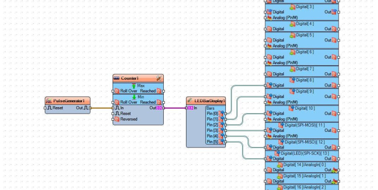
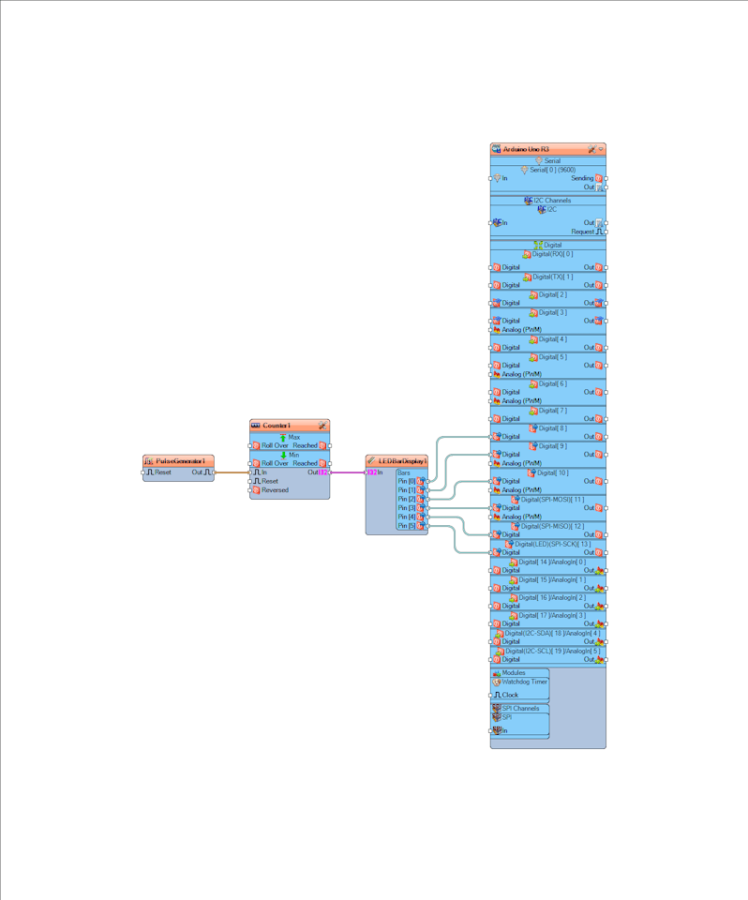
- Connect "PulseGenerator1" pin [Out] to "Counter1" pin [In]
- Connect "Counter1" pin [Out] to "LEDBarDisplay1" pin [In]
- Connect "LEDBarDisplay1" pin [0] to Arduino digital pin [8]
- Connect "LEDBarDisplay1" pin [1] to Arduino digital pin [9]
- Connect "LEDBarDisplay1" pin [2] to Arduino digital pin [10]
- Connect "LEDBarDisplay1" pin [3] to Arduino digital pin [11]
- Connect "LEDBarDisplay1" pin [4] to Arduino digital pin [12]
- Connect "LEDBarDisplay1" pin [5] to Arduino digital pin [13]
1 / 2
In Visuino, at the bottom click on the "Build" Tab, make sure the correct port is selected, then click on the "Compile/Build and Upload" button.
Step 7: PlayIf you power the Arduino module the LEDs on the indicator module will start to produce different effects.
Congratulations! You have completed your project with Visuino. Also attached is the Visuino project, that I created for this tutorial, you can download it and open it in Visuino: https://www.visuino.com
Schematics, diagrams and documents
Code
Credits
Related products


Leave your feedback...