
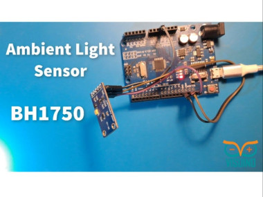
Visuino Bh-1750 Ambient Light Sensor

About the project
In this tutorial you will learn how to use BH-1750 ambient light sensor with Visuino. Watch the Video!
Project info
Difficulty: Easy
Estimated time: 1 hour
License: GNU General Public License, version 3 or later (GPL3+)
Items used in this project
Hardware components

Story
The values from the sensor will be displayed in Visuino Instrument for better visualization.
This project was made by Visuino user Rafał. Visit his youtube channel here: https://www.youtube.com/@Edappl/videos
Step 1: What You Will Need1 / 4
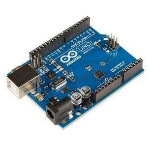
Arduino UNO or Arduino Mega (or any other board)
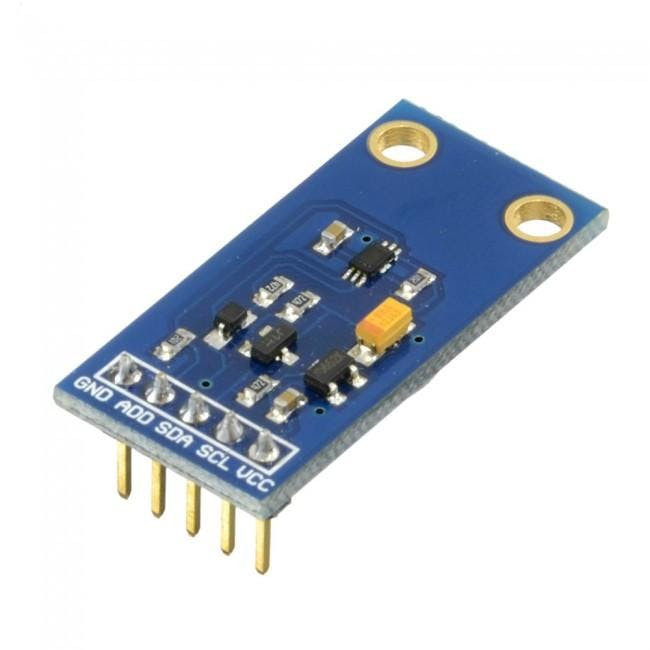
- BH-1750 ambient light sensor
- Visuino program: Download Visuino
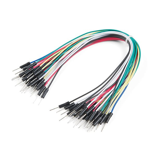
- Jumper wires
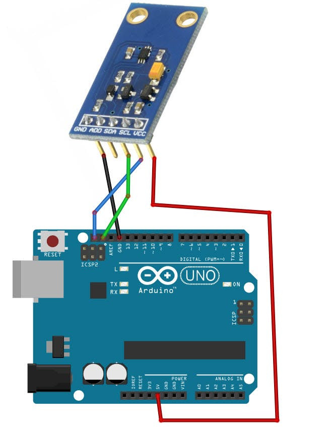
- Connect BH-1750 Sensor pin [SCL] to Arduino pin [SCL]
- Connect BH-1750 Sensor pin [SDA] to Arduino pin [SDA]
- Connect BH-1750 Sensor pin [VCC] to Arduino pin [5v]
- Connect BH-1750 Sensor pin [GND] to Arduino pin [GND]
1 / 2
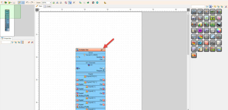
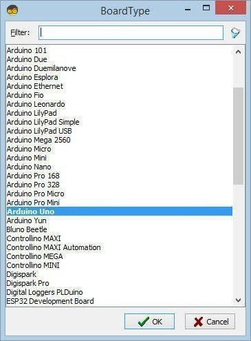
Start Visuino as shown in the first picture Click on the "Tools" button on the Arduino component (Picture 1) in Visuino When the dialog appears, select "Arduino UNO" as shown on Picture 2
Step 4: In Visuino Add Components1 / 5
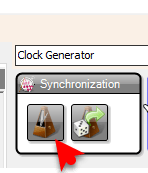
- Add "Clock Generator" component
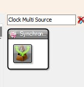
- Add "Clock Multi Source" component
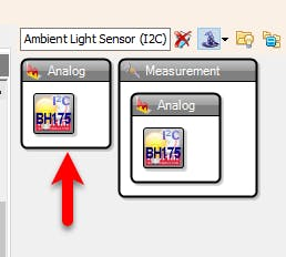
- Add "ROHM BH1750 Ambient Light Sensor (I2C)" component
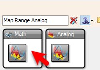
- Add "Map Range Analog" component
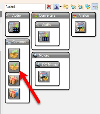
- Add "Packet" component
1 / 5
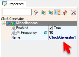

- Select "ClockGenerator1" and in the properties window set "Frequency" to 10
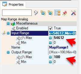
- Select "MapRange1" and in the properties window set "Input Range" > "Max" to 54612 and "Output Range" > "Max" to 100
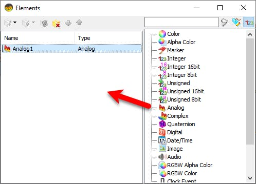
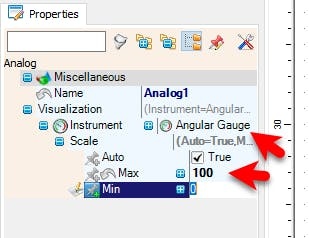
- Double click on "Packet1" and in the Elements window drag "Analog" to the left side and in the properties window set "Visualization" > "Scale" > "Max" to 100
Note: you can adjust the MapRange1 output Max and Packet1 Analog1 Scale Max according to your needs
also you can change the "Instrument" to something else
Step 6: In Visuino Connect Components1 / 2
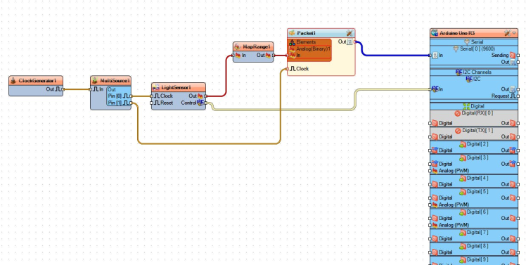
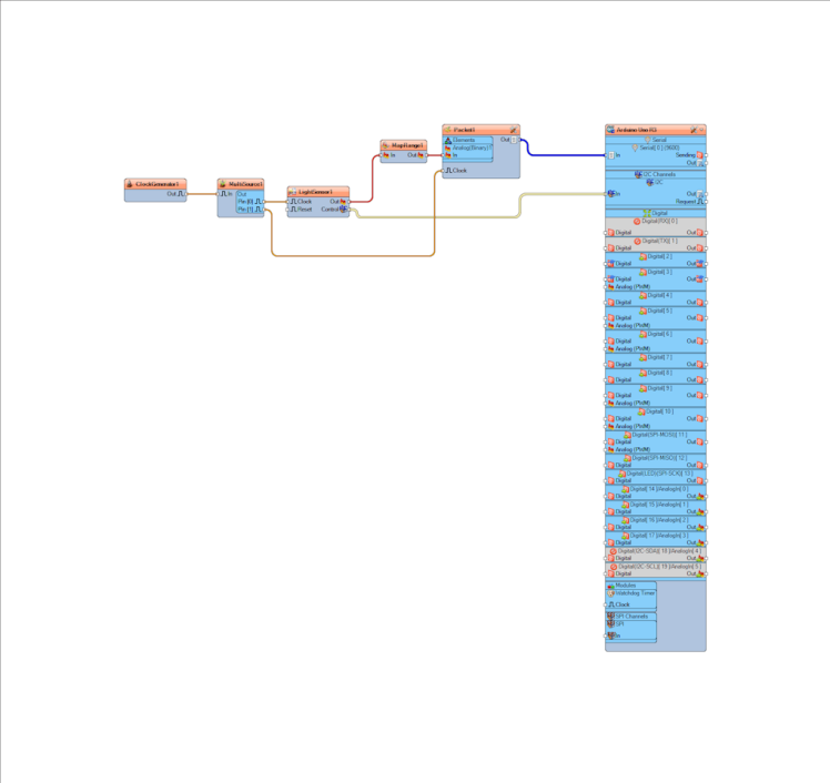
- Connect "ClockGenerator1" pin [Out] to "MultiSource1" pin [In]
- Connect "MultiSource1" pin [0] to "LightSensor1" pin [Clock]
- Connect "MultiSource1" pin [1] to "Packet1" pin [Clock]
- Connect "LightSensor1" pin [Out] to "MapRange1" pin [In]
- Connect "LightSensor1" pin [I2C] to Arduino pin [I2C]
- Connect "MapRange1" pin [Out] to "Packet1" > "Analog1" pin [In]
- Connect "Packet1" pin [Out] to Arduino serial 0 pin [In]
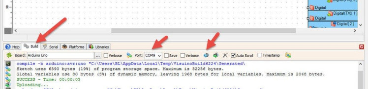
In Visuino, at the bottom click on the "Build" Tab, make sure the correct port is selected, then click on the "Compile/Build and Upload" button.
Step 7: Play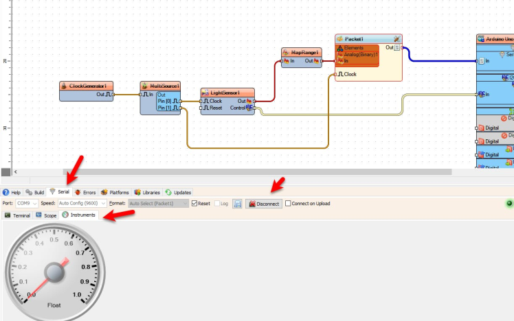
If you power the Arduino module, at the bottom click on the "Serial" Tab > "Instruments", make sure you selected the correct port and click "Connect" button. You should start to see the values from the sensor.
Since the "ClockGenerator1" frequency is 10Hz we are getting values 10x every second, you can adjust the Frequency of the "ClockGenerator1" in the properties window.
Congratulations! You have completed your project with Visuino. Also attached is the Visuino project, that I created for this Instructable, you can download it here and open it in Visuino: https://www.visuino.eu
Schematics, diagrams and documents
Code
Credits
Related products


Leave your feedback...