
Adafruit Mprls - Pressure Sensor Using Visuino Custom Code

About the project
In this tutorial we are going to read the values from a Pressure Sensor Adafruit MPRLS by using a Custom Code component in Visuino Pro.
Project info
Difficulty: Moderate
Platforms: Adafruit, Arduino, Visuino
Estimated time: 1 hour
License: GNU General Public License, version 3 or later (GPL3+)
Items used in this project
Hardware components

Story
Custom Code component in Visuino Pro allows us to add any Arduino code to the Visuino project.
Custom Code component in Visuino Pro is very useful if you need to add some sensor that is not yet supported in Visuino but you already have the code for it, or to just experimenting by adding your own code to the project.
Custom code in Visuino PRO is solving nearly 100% of all the missing functionality in Visuino Standard version.
More about Visuino Pro here
Here are also some very good tutorials on how to use a Custom Code component:
Getting started with the Custom Code component
Step 1: What You Will Need1 / 5
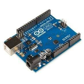
- Arduino UNO (Or any other Arduino)
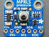
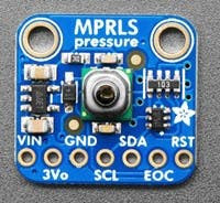
- Adafruit MPRLS Ported Pressure Sensor
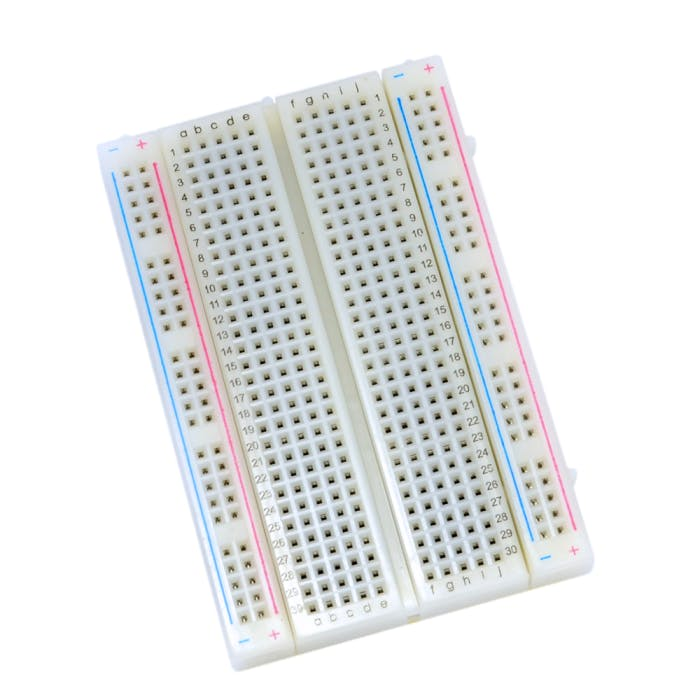
- Breadboard
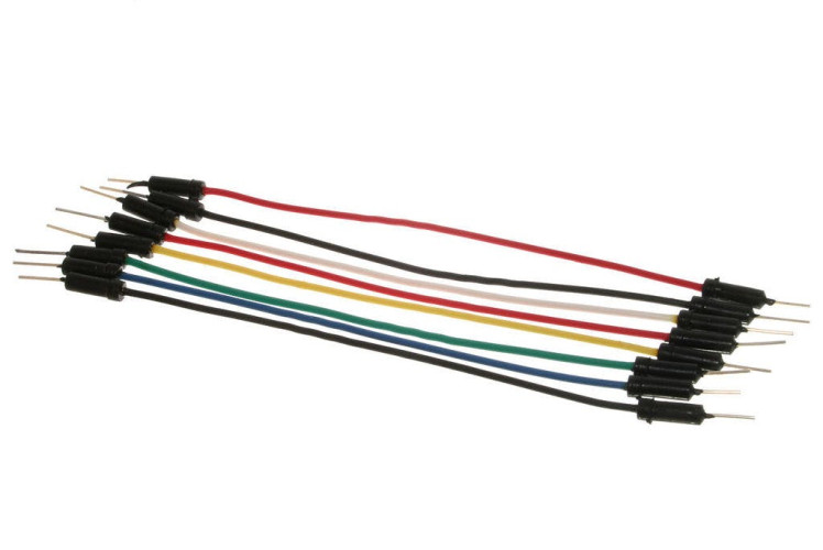
- Jumper wires
- Visuino Pro software: Download here
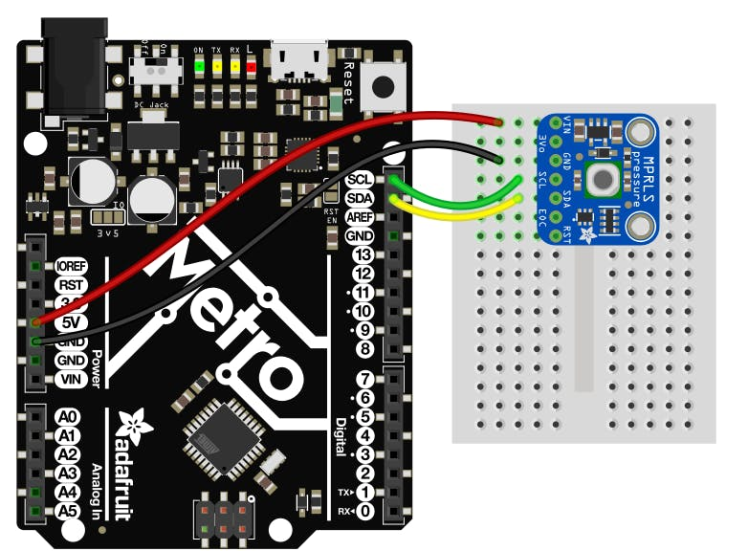
- Connect Vin to the power supply, 3-5V is fine. Use the same voltage that the microcontroller logic is based off of. For most Arduinos, that is 5V
- Connect GND to common power/data ground
- Connect the SCL pin to the I2C clock SCL pin on your Arduino. On an UNO & '328 based Arduino, this is also known as A5, on a Mega it is also known as digital 21 and on a Leonardo/Micro, digital 3
- Connect the SDA pin to the I2C data SDA pin on your Arduino. On an UNO & '328 based Arduino, this is also known as A4, on a Mega it is also known as digital 20 and on a Leonardo/Micro, digital 2
The MPRLS has a default I2C address of 0x18 and cannot be changed!
More here
Step 3: Install Arduino Libraries1 / 2
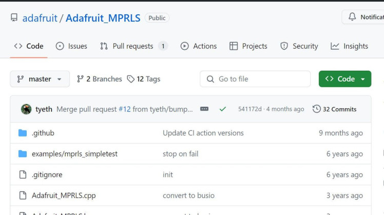
Go to https://github.com/adafruit/Adafruit_MPRLS and download Adafruit_MPRLS Arduino Library
Extract the to your Arduino Libraries folder, usually it looks something like this: C:UsersUserDocumentsArduinolibraries
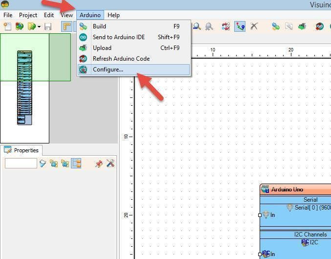
You can also find the Path if you in Visuino click on the Menu>Arduino>Configure and see it under "Arduino Library Directory" (see attached screenshot)
Step 4: Start Visuino Pro, and Select the Arduino UNO Board Type1 / 2
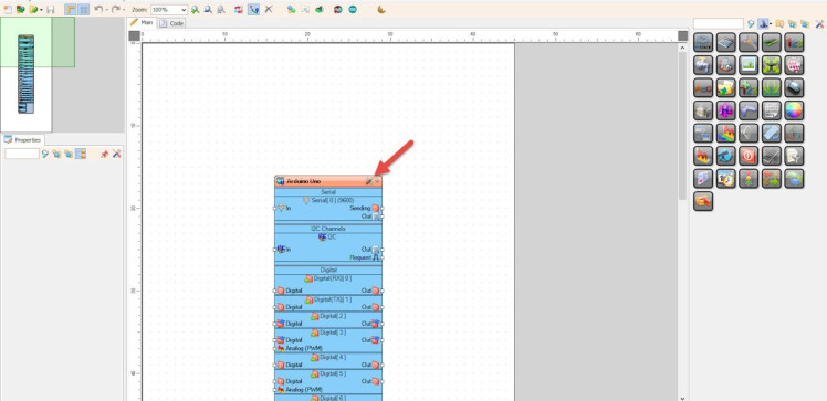
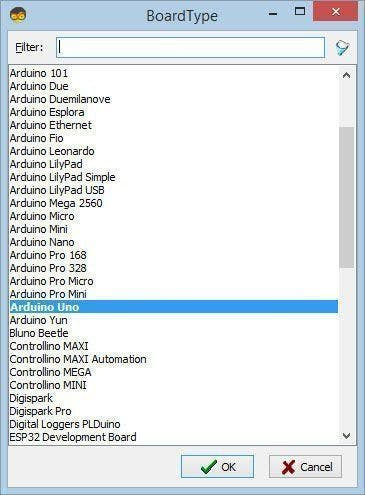
Start Visuino as shown in the first picture Click on the "Tools" button on the Arduino component (Picture 1) in Visuino When the dialog appears, select "Arduino UNO" as shown on Picture 2
Step 5: In Visuino Add Components1 / 2
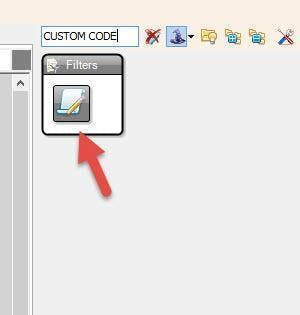
- Add "Custom Code" component
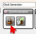
- Add "Clock Generator" component
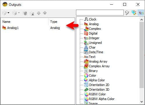
- Double click on the "CustomCode1" and in the "Outputs" window drag "Analog" to the left side
- close the "Outputs" window
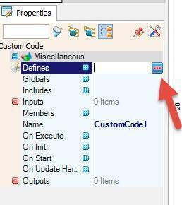
Select "CustomCode1" and in the properties window select "Includes" and Click on the 3dots button
In the "Includes" window add this code:
#include <Adafruit_MPRLS.h>And Close the "Includes" window
Select "CustomCode1" and in the properties window select "Members" and Click on the 3dots button
In the "Members" window add this code:
double pressure_hPa;
Adafruit_MPRLS mpr;
And Close the "Members" window
Select "CustomCode1" and in the properties window select "On Init" and Click on the 3dots button
In the "On Init" window add this code:
mpr.begin();And Close the "On Init" window
Select "CustomCode1" and in the properties window select "On Execute" and Click on the 3dots button
In the "On Execute" window add this code:
{
double pressure_hPa = mpr.readPressure();
Analog1.Send( pressure_hPa);
}
And Close the "On Execute" window
Step 8: In Visuino Connect Components1 / 2

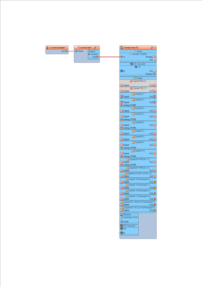
- Connect "ClockGenerator1" pin [Out] to "CustomCode1" pin [Clock]
- Connect "CustomCode1" > "Analog1" pin [Out] to "Arduino" Serial pin [In]
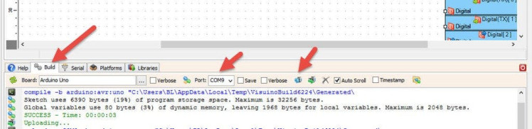
In Visuino, at the bottom click on the "Build" Tab, make sure the correct port is selected, then click on the "Compile/Build and Upload" button.
Step 10: PlayIf you power the Arduino module, at the bottom click on the "Serial" Tab, make sure you selected the correct port and click "Connect" button. You should start to see the pressure values in the serial monitor.
Since the "ClockGenerator1" frequency is 1Hz we are getting values every second, you can adjust the Frequency of the "ClockGenerator1" in the properties window.
Congratulations! You have completed your project with Visuino. Also attached is the Visuino project, that I created for this Instructable, you can download it here and open it in Visuino: https://www.visuino.eu
Schematics, diagrams and documents
Code
Credits
Related products


Leave your feedback...