
Send Sms Using Sim900 Gsm Shield & Arduino - Visuino Tutoria

Made by Ron / Communication / Displays / Security / Sensors
About the project
In this tutorial you will learn how to send sms using the SIM900 GSM Shield and Visuino. Watch the Video!
Project info
Difficulty: Easy
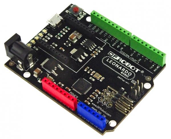
Platforms: DFRobot, Digilent, Visuino
Estimated time: 1 hour
License: GNU General Public License, version 3 or later (GPL3+)
Items used in this project
Hardware components

Story
With one button we will set the GSM shield into text messages Mode, set the number and the text message, with the second button we are going to send sms.
You will also learn how to use the "Serial Software" component in Visuino.
Also check out this tutorial: Make a Phone Call Using the SIM900 GSM Shield & Arduino - Visuino Tutorial
Step 1: What You Will Need1 / 8
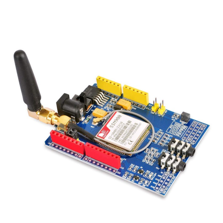
- SIM900 GSM Shield
- Sim card (You should disable the pin request on the sim card before using it with the GSM shield)
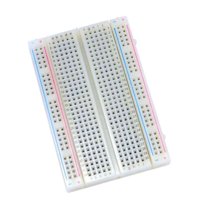
- Breadboard
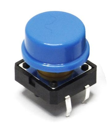
- 2X button
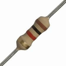
- 2X 1Kohm resistor
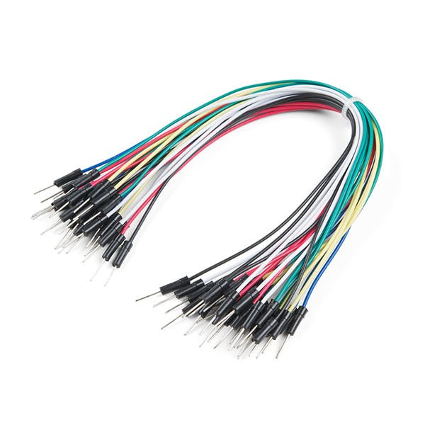
- Jumper wires
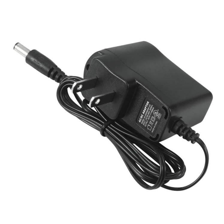
- 5V power supply with enough amps for the shield
- Visuino program: Download Visuino
1 / 3
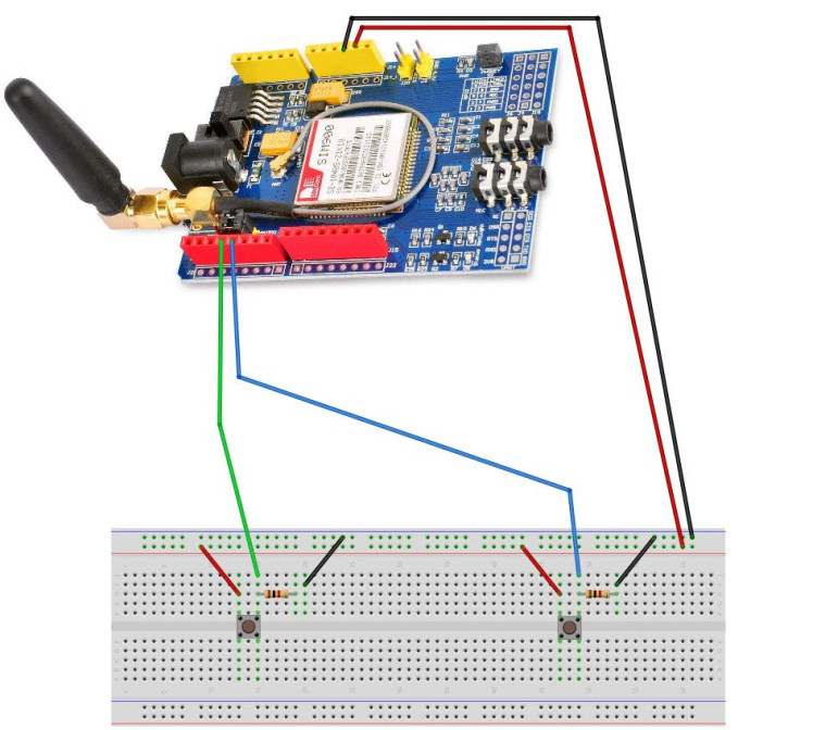
- Connect the SIM900 GSM Shield to the Arduino
- Connect Arduino pin [5V] to breadboard positive pin [Red line]
- Connect Arduino pin [GND] to breadboard negative pin [Black line]
- Connect Arduino Digital pin [2] to button1 on the breadboard and to the Resistor1
- Connect other side of the resistor1 to the breadboard pin [GND]
- Connect Other pin of the button1 to the breadboard positive pin [5V]
- Connect Arduino Digital pin [2] to button1 on the breadboard and to the Resistor1
- Connect other side of the resistor1 to the breadboard pin [GND]
- Connect Other pin of the button1 to the breadboard positive pin [5V]
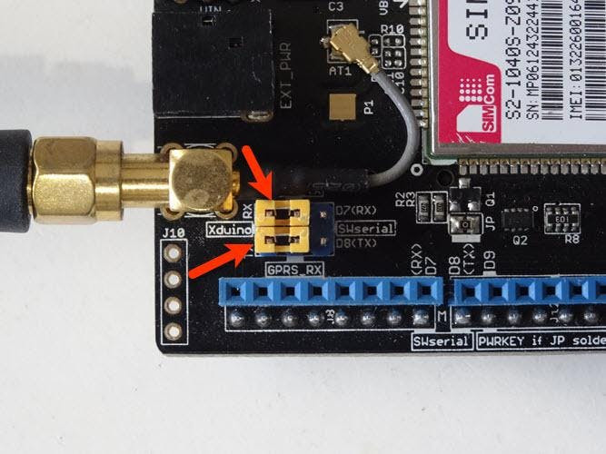
- Connect with the Jumpers on the shield pins D8(RX) & D7(TX) like you see it on the picture
- Make sure that the antenna is connected to the shield
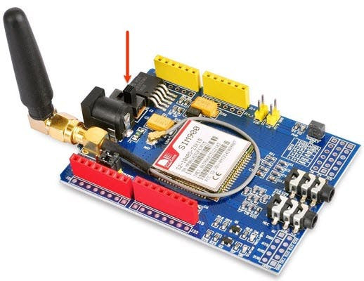
- Connect the 5V Power Supply to the shield, and set the switch on the shield to the External Power (See the picture)
- Once the Power is connected hold the Power button for 2s
- Once the connection with the Network is established the LED will blink every 3s
1 / 2
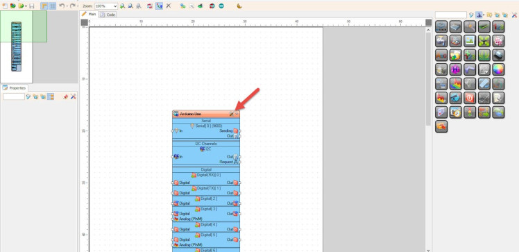
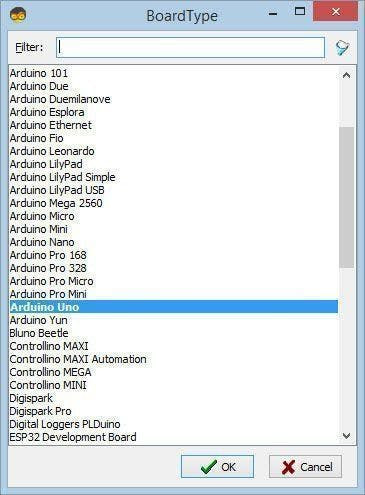
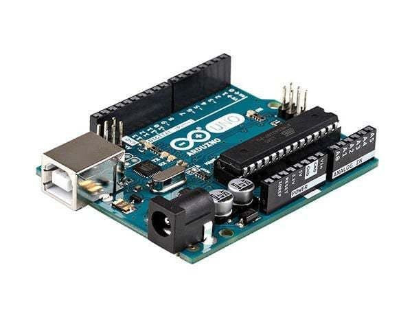
Start Visuino as shown in the first picture Click on the "Tools" button on the Arduino component (Picture 1) in Visuino When the dialog appears, select "Arduino UNO" as shown on Picture 2
Step 4: In Visuino Add Components1 / 6
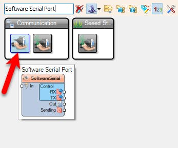
- Add "Software Serial Port" component
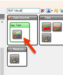
- Add "Add "Text Value" component
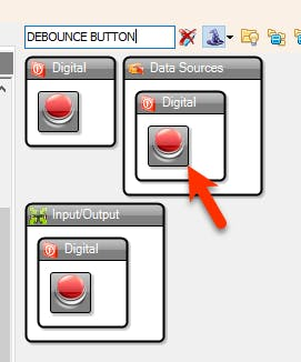
- Add 2X "Debounce Button" component
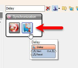
- Add 3X "Delay" component
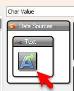
- Add "Char Value" component
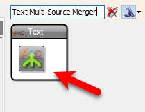
- Add "Text Multi-Source Merger" component
1 / 6
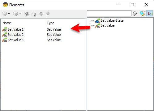

- Double click on the "TextValue1" and in the Elements window
- Command to set GSM shield to text mode: drag "Set Value" to the left side and in the properties window set "Value" to AT+CMGF=1
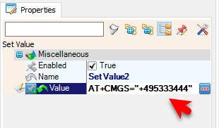
- Command to set Phone number (International Format): drag another "Set Value" to the left side and in the properties window set "Value" to AT+CMGS="+495XXXXXX"
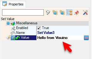
- Command to set Text Message: In the Elements window Drag another "Set Value" to the left side and in the properties window set "Value" to Hello from Visuino
- Close the Elements window
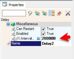
- Select "Delay2" and in the properties window set "Interval (uS)" to 2000000
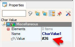
- Select "CharValue1" and in the properties window set "Value" to #26
1 / 2
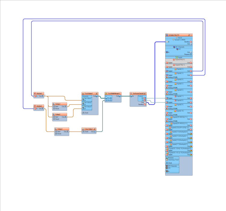
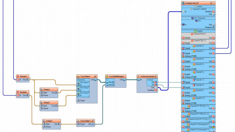
- Connect Arduino digital pin [2] to "Button1" pin [In]
- Connect Arduino digital pin [3] to "Button2" pin [In]
- Connect "Button1" pin [Out] to "TextValue1" > "Set Value1" pin [In]
- Connect "Button1" pin [Out] to "Delay1" pin [Start]
- Connect "Button1" pin [Out] to "Delay2" pin [Start]
- Connect "Delay1" pin [Out] to "TextValue1" > "Set Value2" pin [In]
- Connect "Delay2" pin [Out] to "TextValue1" > "Set Value3" pin [In]
- Connect "Button2" pin [Out] to "Delay3" pin [Start]
- Connect "Delay3" pin [Out] to "CharValue1" pin [Clock]
- Connect "TextValue1" pin [Out] to "TextMultiMerger1" pin [0]
- Connect "CharValue1" pin [Out] to "TextMultiMerger1" pin [1]
- Connect "TextMultiMerger1" pin [Out] to "SoftwareSerial1" pin [In]
- Connect "SoftwareSerial1" pin [RX] to Arduino Digital pin [7]
- Connect "SoftwareSerial1" pin [TX] to Arduino Digital pin [8]
Optional if you want to monitor response from the GSM shield: Connect "SoftwareSerial1" pin [Out] to Arduino Serial pin [In]
Step 7: Generate, Compile, and Upload the Arduino Code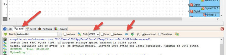
In Visuino, at the bottom click on the "Build" Tab, make sure the correct port is selected, then click on the "Compile/Build and Upload" button.
Step 8: PlayWhen you power the Shield wait a bit for the connection with the network to be established, once the connection is established the LED on the shield will blink every 3s.
Now you can press a button and the GSM shield will go into Text Messages Mode and it will set the phone number and set the Text message. To send SMS just press the other button.
Congratulations! You have completed your GSM project with Visuino. Also attached is the Visuino project, that I created for this Tutorial. You can download and open it in Visuino: https://www.visuino.eu
Schematics, diagrams and documents
Code
Credits
Related products


Leave your feedback...