
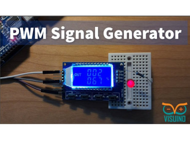
How To Use Pwm Signal Generator Module With Visuino

Made by Ron / Automotive / Communication / Environmental Sensing / Robotics / Sensors
About the project
In this tutorial we will learn how to control a PWM Signal Generator Module XY-LPWM with Visuino. Watch the Video!
Project info
Difficulty: Easy
Estimated time: 1 hour
License: GNU General Public License, version 3 or later (GPL3+)
Items used in this project
Hardware components

Story
Also checkout this tutorial:
: How to Control PWM Signal Generator Module With Arduino & Visuino
Step 1: What You Will Need1 / 6
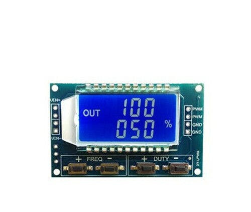
- XY-LPWM or HW-753 PWM Signal Generator Module
- Arduino UNO (or any other Arduino)
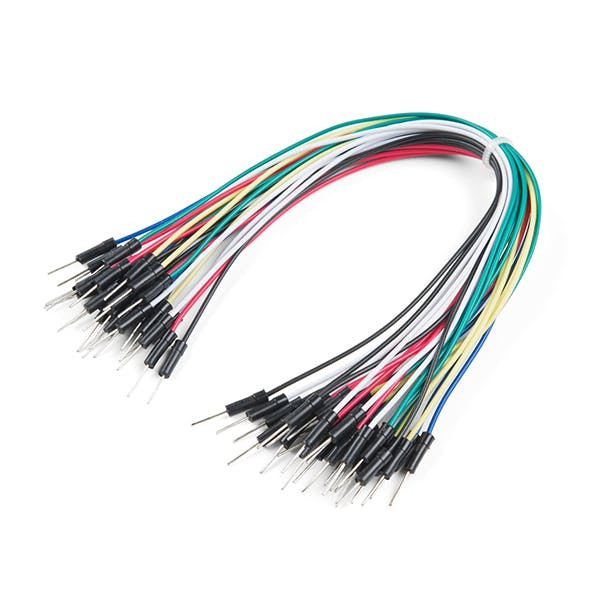
- Jumper wires
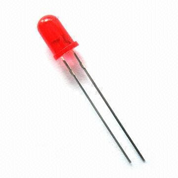
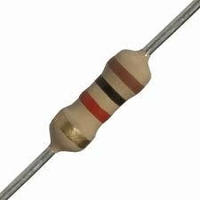
- Optional 1X LED and 1K ohm resistor, Breadboard
- Visuino program: Download Visuino
- Operating Voltage: 3.3 to 30 Volts
- Frequency Range: 1 Hz to 150 kHz
- 0-100% duty cycle
- Frequency Accuracy: Approximately 2% accuracy within each range
- Signal Load Capacity: Output current ranging from 5 to 30 mA
- Output Amplitude: PWM amplitude matches the supply voltage
- Operating Temperature Range: -20 to +70 degrees Celsius
- Communication Standard: 9600 bps Data bits: 8
1 / 2
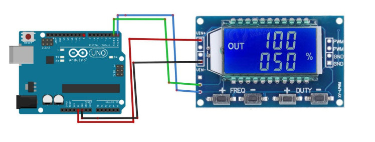
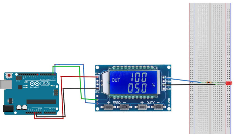
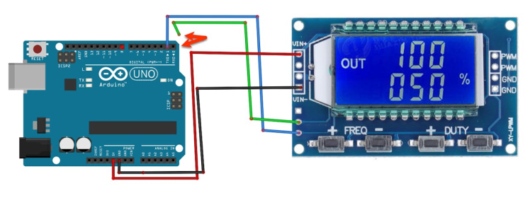
- Connect Arduino pin [RX] to the PWM Module pin [TX]
- Connect Arduino pin [TX] to the PWM Module pin [RX]
- Connect Arduino pin [5V] to the PWM Module pin [VIN+]
- Connect Arduino pin [GND] to the PWM Module pin [VIN-]
When using LED:
- Connect PWM Module pin [PWM] to 1K ohm resistor
- Connect 1K ohm resistor to LED positive pin [+]
- Connect PWM Module pin [GND] to LED negative pin [-]
1 / 2
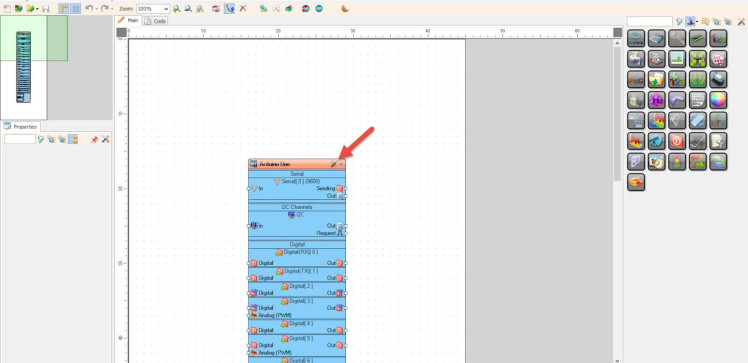
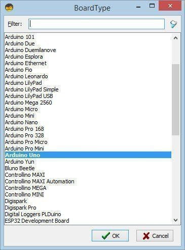
Start Visuino as shown in the first picture Click on the "Tools" button on the Arduino component (Picture 1) in Visuino When the dialog appears, select "Arduino UNO" as shown on Picture 2
Step 5: About the Visuino "PWM Signal Generator Module" Component1 / 2
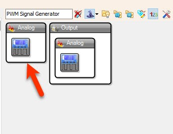
You can find the component in the Component Window if you type "PWM Signal Generator Module"
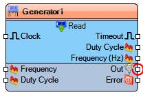
- The component has a pin "Frequency" where you can connect any Analog pin and send the Frequency in Hz, example for the frequency of 10KHz you would need to set the value to 10000
- Pin "Duty Cycle" will set the Duty Cycle on the output from 0 to 100%, to set it correctly you need to connect the Analog value to it from 0 to 1 where 0 is 0%, 0.3 is 30% or 1 is 100%
- To get the current Frequency and Duty Cycle from the module you need to connect some clock signal to the pin [Clock], and the values will be sent on the output pins "Frequency" and "Duty Cycle".
1 / 6

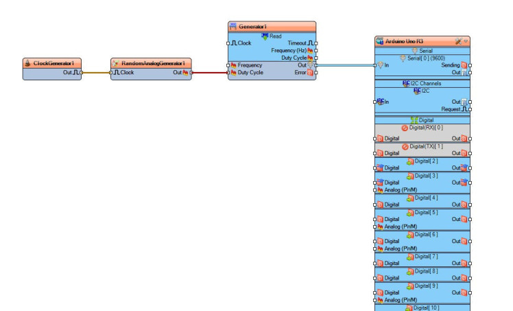
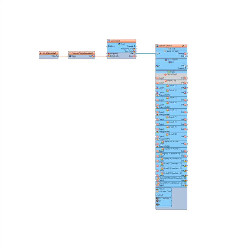
- Add "PWM Signal Generator Module" component
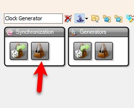
- Add "Clock Generator" component
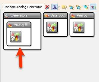
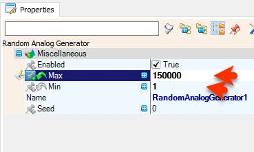
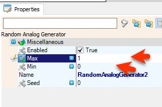
- Add "Random Analog Generator" component
- Select "RandomAnalogGenerator1" and in the properties window set "Max" to 150000 and "Min" to 1
- If you are going to connect the LED set "Max" to 5 so that you can see it blinking
1 / 2
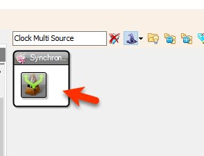
- Connect "ClockGenerator1" pin [Out] to "ClockMultiSource1" pin [In]
- Connect "ClockMultiSource1" pin [0] to "RandomAnalogGenerator1" pin [Clock]
- Connect "ClockMultiSource1" pin [1] to "RandomAnalogGenerator2" pin [Clock]
- Connect "RandomAnalogGenerator1" pin [Out] to "Generator1" pin [Frequency]
- Connect "RandomAnalogGenerator2" pin [Out] to or to "Generator1" pin [Duty Cycle]
- Connect "Generator1" pin [Out] to Arduino Serial pin [In]
1 / 2
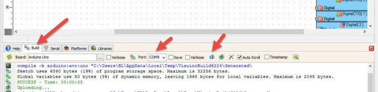
Before Uploading Disconnect RX pin on Arduino and connect it back after the Upload.
In Visuino, at the bottom click on the "Build" Tab, make sure the correct port is selected, then click on the "Compile/Build and Upload" button.
Step 9: PlayIf you power the Arduino module the PWM it will start to change the Frequency and the Duty Cycle every second.
Congratulations! You have completed your project with Visuino. Also attached is the Visuino project, that I created for this tutorial, you can download it and open it in Visuino: https://www.visuino.com
Step 10: To Read the Values From the Module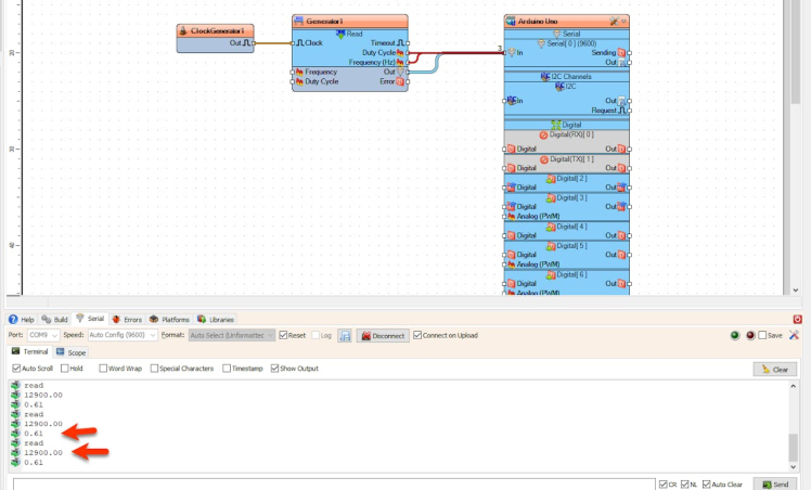
- Connect "ClockGenerator1" pin [Out] to "Generator1" pin [Clock]
- Connect "Generator1" pin [Frequency] to Arduino Serial pin [In]
- Connect "Generator1" pin [Duty Cycle] to Arduino Serial pin [In]
- Connect "Generator1" pin [Out] to Arduino Serial pin [In]
Upload the project (Make sure do disconnect the Arduino RX pin when uploading) and Connect in the serial window to the Arduino board and you should see the current Frequency and the Duty Cycle. If you press the buttons on the module to change the Frequency the change will also be seen in the serial window.
Schematics, diagrams and documents
Code
Credits
Related products


Leave your feedback...