
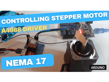
Control Nema 17 Stepper Motor With A4988 Driver And Arduino

Made by Ron / 3D Printing / Automotive / Drones / Home Automation / Robotics
About the project
In this tutorial we will use stepper driver A4988, NEMA17 stepper motor, Arduino Uno and Visuino to run a stepper motor.
Items used in this project
Hardware components

Story
1 / 7

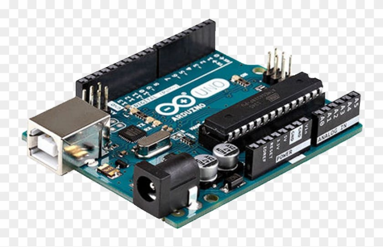

- Arduino UNO (Or any other Arduino)
- Stepper motor NEMA 17
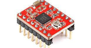
- A4988 Stepper Motor Driver or (DRV8825)
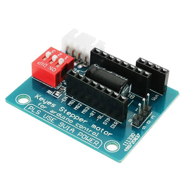
- Optional DRV8825/A4988 Stepper Driver Expansion Module
- Jumper wires
- Breadboard
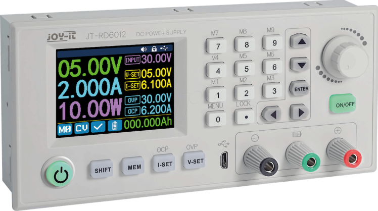
- Power Supply 12V
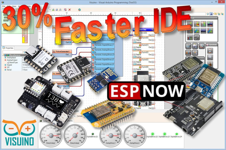
- Visuino program: Download Visuino

Thank you PCBWay for supporting this tutorial and helping users learn more about electronics.
What I like about the PCBWay is that you can get 10 boards for approximately $5 which is really cost effective for professional made boards, not to mention how much time you save!
Go check them out here. They also offer a lot of other stuff in case you might need it like assembly,3D printing,CNC machining and a lot more.
Step 3: The Circuit1 / 2

- Arduino Digital Pin 2 will be used for Steps
- Arduino Digital Pin 3 will be used for Motor Direction
If using a Stepper Motor Driver Shield:
- Connect Motor Shield GND pin to Arduino negative pin [GND]
- Connect Motor Shield [5V] pin to Arduino positive pin [5V]
- Connect Motor Shield GND pin to Power Supply negative pin [GND]
- Connect Motor Shield [9V] pin to Power Supply positive pin [+]
- Connect Motor Shield pin[S] to Arduino digital pin [2]
- Connect Motor Shield pin[D] to Arduino digital pin [3]
- Connect stepper motor as shown on the picture.
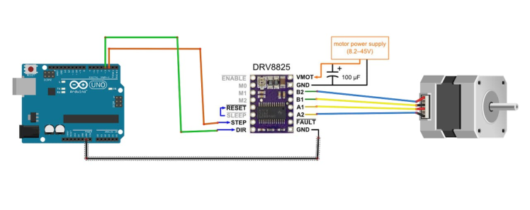
If using a Stepper Motor Driver 8825:
- Connect DRV8825 GND pin to Arduino negative pin [GND]
- Connect DRV8825 DIR pin to Arduino digital pin [3]
- Connect DRV8825 STEP pin to Arduino digital pin [2]
- Connect Power Supply for the motor to DRV8825 VMOT and GND
- Connect Capacitor across VMOT and GND
- Connect stepper motor as shown on the picture.
1 / 2
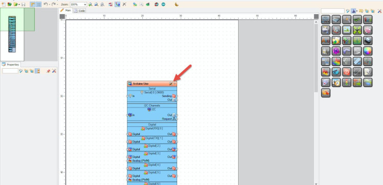

Start Visuino as shown in the first picture Click on the "Tools" button on the Arduino component (Picture 1) in Visuino When the dialog appears, select "Arduino UNO" as shown on Picture 2
Step 5: In Visuino Add Components1 / 6
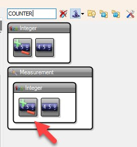
- Add "Counter" component
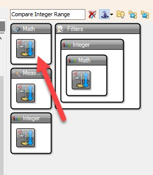
- Add "Compare Integer Range" component
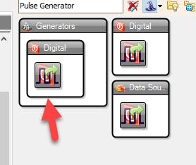
- Add "Pulse Generator" component
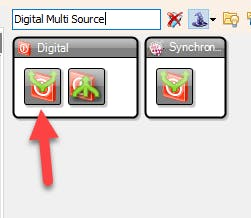
- Add "Digital Multi Source" component
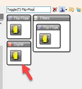
- Add "Toggle(T) Flip-Flop" component
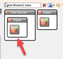
- Add "Digital (Boolean) Value" component
1 / 3
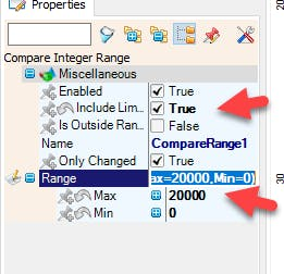

How to set the amount of steps, for example 20000 steps:
- Select "CompareRange1" component and in the properties set "Include Limits" to True and "Range" > "Max" to 20000
This means that as long as the number is within the range of 20000 the Motor should run
How to set the Motor Direction:
- To set the motor direction the "Value" of the "DigitalValue1" in the properties window should be either True or False
How to set the Motor Speed:
- Select "PulseGenerator1" and in the properties window set "Frequency" to 1200 or less, you can set it to a higher number but the motor might have problems spinning at that speed
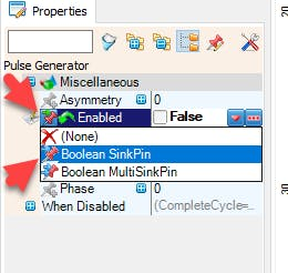
- Select "PulseGenerator1" and in the properties window select "Enabled" and click on the Pin Icon and select Boolean SinkPin
1 / 2
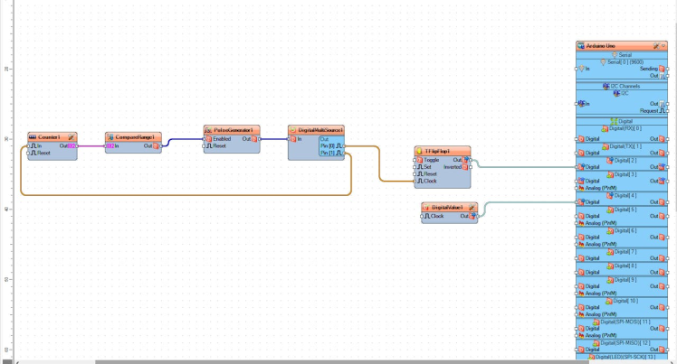
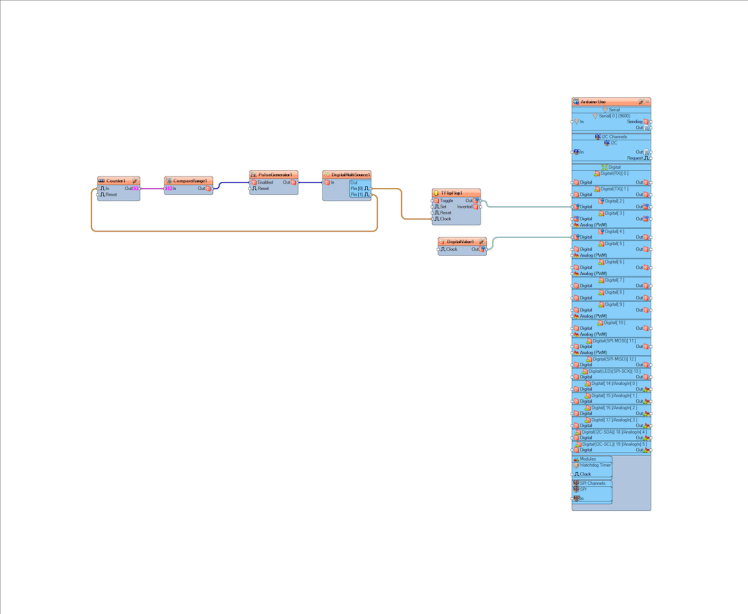
- Connect "Counter1" Pin [Out] to "CompareRange1" Pin [In]
- Connect "CompareRange1" Pin[Out] to "PulseGenerator1" Pin [Enabled]
- Connect "PulseGenerator1" Pin[Out] to "DigitalMultiSource1" Pin [In]
- Connect "DigitalMultiSource1" Pin[0] to "TFlipFlop1" Pin [Clock]
- Connect "DigitalMultiSource1" Pin[1] to "Counter1" Pin [In]
- Connect "TFlipFlop1" Pin[Out] to Arduino Board Digital Pin [2]
- Connect "DigitalValue1" Pin[Out] to Arduino Board Digital Pin [3]
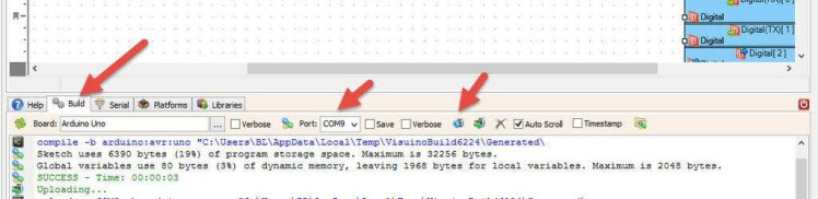
In Visuino, at the bottom click on the "Build" Tab, make sure the correct port is selected, then click on the "Compile/Build and Upload" button.
Step 9: PlayIf you power the Arduino module, The motor will do will start to run and when it reaches a certain amount of steps it will stop.
Congratulations! You have completed your project with Visuino. Also attached is the Visuino project, that I created for this Instructable, you can download it here and open it in Visuino: https://www.visuino.eu
Schematics, diagrams and documents
Code
Credits
Related products


Leave your feedback...