


DFRobot Gravity 10DOF IMU: Motion, Heading and Altitude
Your rover reaches a ramp. You want to log how its body tilts, how quickly it turns and whether it gains elevation. An accelerometer and gyroscope cover much of the movement, but magnetic-field and pressure measurements add useful context. The DFRobot Gravity 10DOF IMU sensor, brings those inputs together on one small board.
It combines Bosch BMI323, BMM350 and BMP581 sensors with a Gravity connector, an onboard controller and a shared software library. That saves you from bringing up three separate breakouts. The interesting part is turning their readings into something your project understands. Calibration, mounting and your application code still decide whether a measurement becomes a useful heading or elevation-change estimate.
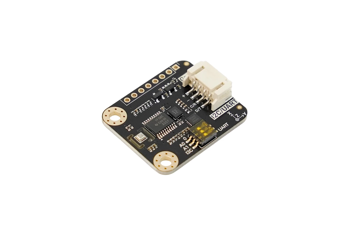
What is the DFRobot Gravity 10DOF IMU?
An inertial measurement unit, or IMU, measures acceleration and angular rate. In this product category, extra sensing channels are commonly included in the DOF count. SEN0696 supplies three acceleration axes, three angular-rate axes, three magnetic-field axes and one pressure channel. That makes ten.
Here, 10DOF is sensing-channel shorthand. It does not mean ten independent mechanical degrees of freedom or a ready-made position output. DFRobot positions this Gravity 10DOF module for quick evaluation and prototyping. It suits sensor lessons, portable loggers and robotics experiments where you want several measurements without a small forest of breakout boards.
Specifications at a glance
The component ranges below describe what each sensor measures. The connections and power specifications apply to the complete Gravity module.
| Item | SEN0696 specification |
|---|---|
| Motion sensor | Bosch BMI323, three-axis acceleration and three-axis angular rate, both 16-bit |
| Acceleration ranges | ±2, ±4, ±8 or ±16 g |
| Angular-rate ranges | ±125, ±250, ±500, ±1000 or ±2000 degrees/s |
| Magnetic sensor | Bosch BMM350, three axes, ±2000 µT |
| Pressure sensor | Bosch BMP581, 300–1250 hPa, equivalent to 30–125 kPa |
| Host interfaces | Selectable I2C or UART |
| Module I2C addresses | 0x4A by default, selectable 0x4B, 0x4C or 0x4D |
| Supply and current | 3.3–5 V input. DFRobot lists 3.59 mA operating current, not a value guaranteed for every configuration. |
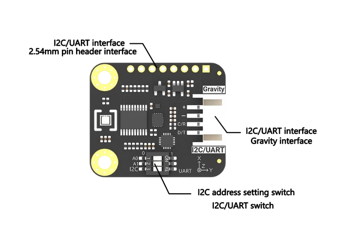
| Connections and size | PH2.0 four-pin Gravity connector, 2.54 mm header holes, four interrupt outputs, 32 × 27 mm PCB |
Sources: SEN0696 module specifications and pinout, plus Bosch’s BMI323, BMM350 and BMP581 documentation.
The selectable addresses belong to the module’s controller, rather than the individual Bosch chips. Likewise, a sensor’s output data rate, or ODR, describes its internal measurement updates. It does not tell you how many complete ten-channel readings your host will receive. Firmware, polling, transport and processing all affect that path.
What the three Bosch sensors add to your project
Each sensor answers a different question. Keeping those questions separate makes your first data plots much easier to understand.
BMI323: movement and rotation
The BMI323 combines an accelerometer with a gyroscope. Acceleration readings help describe vibration and tilt under suitable conditions. Angular-rate readings show how quickly the board rotates. For a rover, you could compare a slow body lean with a sudden bump.
A stationary accelerometer still responds to gravity, distributed across its axes according to orientation. Movement complicates tilt estimation because acceleration from the vehicle mixes with that gravity reference. The gyro helps describe rapid rotation, but small zero-rate errors accumulate when you integrate its readings into angles.
BMM350: a magnetic reference for heading
The BMM350 magnetometer measures magnetic field in microtesla. Its tunneling magnetoresistance, or TMR, sensing technology gives your software another input for heading estimation. A rotating desk display is a manageable place to explore that.
Useful compass behavior needs calibration and, when the board tilts, suitable tilt compensation. Motors, magnets, speakers, steel and high-current wiring can distort the local field. A neat sensor mount beside a rover’s motor may be electrically convenient and magnetically troublesome.
BMP581: pressure changes that suggest elevation changes
Pressure generally falls as altitude increases. The BMP581 pressure sensor therefore adds a useful input for an elevation logger. Software converts pressure into an estimated height using a reference and atmospheric assumptions.
Bosch specifies typical relative pressure accuracy of ±6 Pa within 700–1100 hPa at 15–55 °C. Relative accuracy, absolute accuracy, noise and digital resolution are different quantities. None alone promises centimeter-accurate absolute height. Weather, airflow, temperature behavior and enclosure ventilation all matter when you leave the bench.
Getting started with I2C, UART and the GUI
Start with DFRobot’s Arduino I2C example, which uses a FireBeetle 2 ESP32-C5. I2C is a shared, clocked two-wire bus. It keeps the initial connection straightforward.
- Install the software. Set up Arduino IDE and the correct host-board support. Install both DFRobot_Multi_DOF_IMU and its required DFRobot_RTU dependency.
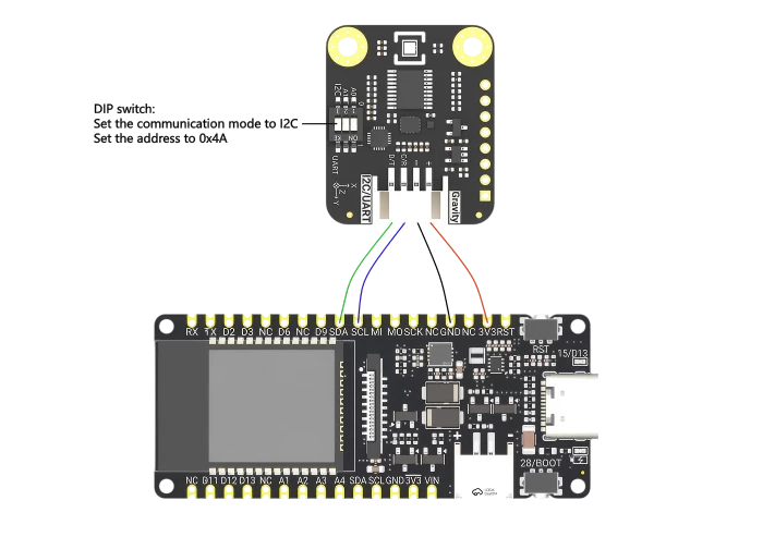
- Set the switches with power disconnected. Select I2C and the default 0x4A address, with A0 and A1 both set to zero. Restart after changing interface mode.
- Connect the example host. Connect + to 3.3 V, − to ground, C/R to SCL and D/T to SDA. DFRobot’s ESP32-C5 mapping uses GPIO10 for SCL and GPIO9 for SDA. These numbers are specific to that host.
- Select the correct model. The example constructs the I2C object with
eSensorModel10DOFand address0x4A. Keep the physical switches and software address aligned. - Choose the output deliberately. The example defaults
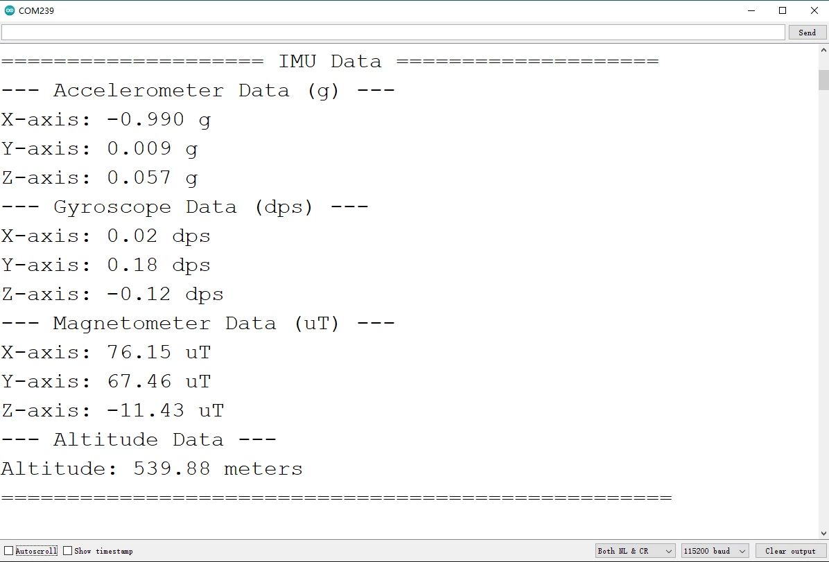
CALCULATE_ALTITUDEtotrueand uses a 540-meter reference. Start withfalseto inspect pressure in pascals. Open Serial Monitor at 115200 baud.
Follow the module schematic and your host’s logic-level requirements. The board’s 3.3–5 V supply rating does not make another controller’s GPIO pins 5 V tolerant. Our project-led development-board guide can help you choose a host before wiring.
UART is an asynchronous serial interface. DFRobot provides a separate UART and interrupt example using Modbus RTU framing. Its interrupt handlers set flags so the main loop can read the measurements. Data-ready events help organize acquisition, but they do not supply continuous fused orientation. The module’s UART pins are not an RS-232 port or an RS-485 transceiver.
For PC visualization, the host-software guide requires a separate RainbowLink V2 adapter. Select UART, the correct serial port and 9600 baud, then follow the initial three-second movement/calibration instruction. The current GUI download is a Windows executable. SEN0696 has no built-in USB connection, and native macOS or Linux GUI support is not established by that package.
Measurements, orientation and calibration
The library’s get10dofData() API returns acceleration in g, angular rate in degrees/s and magnetic field in microtesla. Its final output value is pressure in Pa or calculated altitude in meters, depending on the altitude flag.
Sensor fusion combines measurements to estimate something harder to measure directly, such as orientation. DFRobot advertises fusion visualization in its GUI. That display does not establish an onboard roll/pitch/yaw or quaternion stream for every host. The public register documentation describes measurement and event interfaces. Treat a portrait/landscape event as an event, rather than a complete 3D attitude estimate.
Mount the board securely, record its axis directions and check gyro bias while stationary. Calibrate magnetic measurements in the final installation, away from obvious interference. For elevation logging, retain the pressure samples and validate your conversion against known height changes.
The current Arduino altitude helper uses a standard-atmosphere formula. Its reference-height helper accepts only positive heights and recalculates the pressure adjustment on each read. Do not assume that calling it establishes a fixed starting-pressure baseline.
For context, DFRobot’s engineering report records 0.08 m maximum altitude drift over 15 minutes for Gravity 10DOF in a stationary test at 24 °C after a three-minute warm-up. That is manufacturer evidence of short-term stability under those conditions, rather than independent Electromaker testing or an absolute-altitude guarantee.
Three projects that make sense for this module
These project ideas use the documented measurements as building blocks. You supply the logging, interpretation and application logic.
A rover’s ramp-and-tilt diary
Log acceleration, angular rate and pressure with timestamps as a rover crosses a known ramp. Compare estimated body tilt with pressure-derived height changes. Add wheel encoders if you also need distance. Ramp recognition needs thresholds, filtering and validation, while navigation needs further position information. Start by learning what the traces mean.
A portable motion and elevation logger
Pair SEN0696 with a battery-powered host and storage. Record movement alongside pressure during a walk or stair climb. Keep a consistent mounting orientation and give the pressure sensor suitable ventilation without exposing it to direct gusts. Identifying floors requires extra logic and references. Include the host and storage in your power budget.
A desktop sensor-fusion lesson
Rotate the board slowly and plot each measurement before combining them. Observe gravity moving between accelerometer axes, gyro responses during turns and magnetic readings changing with orientation. Then introduce a fusion algorithm and compare its estimate with the original signals. Our community ESP32 IMU visualization project offers related inspiration using different hardware, rather than compatible SEN0696 code.
Gravity vs Fermion, and when fewer channels are enough
Fermion SEN0697 uses the same sensor trio in a 24 × 19 mm breakout. Its documentation specifies 3.3 V power and I2C, with separate sensor addresses. Choose it when direct sensor configuration and a smaller footprint suit your integration work. Choose Gravity when its connector, controller, UART option and unified workflow save you time.
Channel count should follow the job. A 6DOF module can cover motion and tilt experiments. A 9DOF design adds a magnetic reference for heading algorithms. SEN0696’s pressure channel earns its place when elevation changes are part of the question. Extra measurements bring extra calibration work, so give each one a purpose.
Who should choose SEN0696?
Choose SEN0696 if you want an accessible starting point for experiments that combine movement, magnetic direction and pressure. The main benefit is integration convenience: one connection and library bring three sensor types into your project.
At the November 3, 2026 check, DFRobot’s official SEN0696 purchasing page lists US$19.90. Allow for your host and any evaluation adapter separately. For a quick first experiment, get raw readings over I2C, move the board deliberately and build your interpretation from there. That is where this little collection of sensors starts becoming useful.
Frequently asked questions
Here are the practical distinctions to keep in mind when planning your build.
What does 10DOF mean on SEN0696?
It means nine axis measurements across acceleration, angular rate and magnetic field, plus one pressure channel. It describes the sensing inputs, rather than ten independent mechanical motions or a complete navigation output.
Does it output fused orientation?
The GUI provides an orientation visualization, but the documented measurement API does not itself return Euler angles or quaternions. Verify an exact firmware interface before designing around onboard fused output.
What do I need for the PC display?
DFRobot documents a RainbowLink V2 adapter, UART wiring and its host application at 9600 baud. The supplied GUI package is a Windows executable. The sensor board does not connect directly to USB.
Does pressure give absolute height?
Pressure supports a calculated altitude estimate with a suitable reference and atmospheric assumptions. Weather and installation conditions affect it. It is useful for exploring elevation changes, but does not automatically identify a floor or provide surveyed height.
Which example should Arduino or ESP32 users start with?
Start with the linked I2C example and both required libraries. It documents FireBeetle 2 ESP32-C5 wiring. Adapt the host configuration carefully for another board, and select raw pressure when you want to examine measurements before altitude calculations.
Is there a Raspberry Pi Python path?
Yes. The official repository includes Raspberry Pi Python software and examples. Its compatibility table marks Raspberry Pi 4 and Python 3 as working. That is a separate Linux workflow from Arduino or Raspberry Pi Pico firmware, and does not establish every Pi model or MicroPython port.

Residing on the south coast of England, Rich has spent the last few years building Electomaker.io from the ground up. He is usually found behind a laptop coordinating the rest of the EM team and occasionally finding time to contribute articles to the blog. When not tapping away at a laptop, he can be found either paddleboarding, at the beach, playing golf (badly), or camping with his family.









Leave your feedback...