
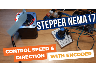
Stepper Motor - Use Encoder To Control Speed & Direction

Made by Ron / 3D Printing / Automotive / Drones / Robotics / Sensors
About the project
In this tutorial we will learn how to use encoder to control the speed and direction of the stepper motor Nema 17 using arduino.
Project info
Difficulty: Easy
Platforms: Arduino, SparkFun, Visuino
Estimated time: 1 hour
License: GNU General Public License, version 3 or later (GPL3+)
Items used in this project
Hardware components

Story
Watch the video!
Step 1: What You Will Need- Arduino UNO (Or any other Arduino)
- Stepper motor NEMA 17
- A4988 Stepper Motor Driver or (DRV8825)
- DRV8825/A4988 Stepper Driver Expansion Module
- Encoder module
- Jumper wires
- Breadboard
- Power Supply 12V
- Visuino program: Download Visuino
1 / 2

Thank you PCBWay for supporting this tutorial and helping users learn more about electronics.
NEW! Now you can get Aluminum PCB & FLEX PCB in their Special Offer!
What I like about the PCBWay is that you can get 10 boards for approximately $5 which is really cost effective for professional made boards, not to mention how much time you save!
Go check them out here. They also offer a lot of other stuff in case you might need it like assembly,3D printing,CNC machining and a lot more.
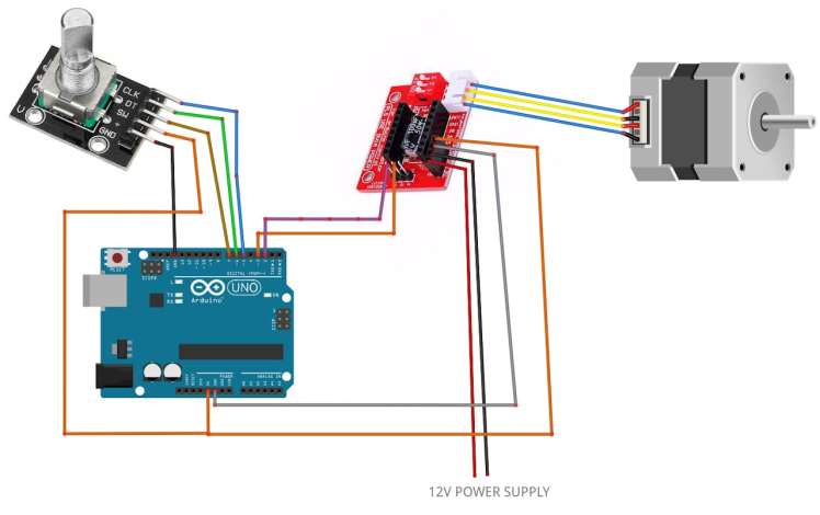
Step 3: The Circuit1 / 2
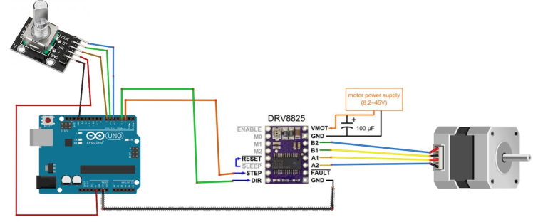
- Arduino Digital Pin 2 will be used for Steps
- Arduino Digital Pin 3 will be used for Motor Direction
If using a Stepper Motor Driver Shield:
- Connect Motor Shield GND pin to Arduino negative pin [GND]
- Connect Motor Shield [5V] pin to Arduino positive pin [5V]
- Connect Motor Shield GND pin to Power Supply negative pin [GND]
- Connect Motor Shield [9V] pin to Power Supply positive pin [+]
- Connect Motor Shield pin[S] to Arduino digital pin [2]
- Connect Motor Shield pin[D] to Arduino digital pin [3]
- Connect stepper motor as shown on the picture.
If using a Stepper Motor Driver 8825:
- Connect DRV8825 GND pin to Arduino negative pin [GND]
- Connect DRV8825 DIR pin to Arduino digital pin [3]
- Connect DRV8825 STEP pin to Arduino digital pin [2]
- Connect Power Supply for the motor to DRV8825 VMOT and GND
- Connect Capacitor across VMOT and GND
- Connect stepper motor as shown on the picture.
Connecting Encoder module:
- Connect Encoder module pin [CLK] to Arduino digital pin [5]
- Connect Encoder module pin [DT] to Arduino digital pin [6]
- Connect Encoder module pin [SW] to Arduino digital pin [7]
1 / 2
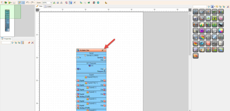

Start Visuino as shown in the first picture Click on the "Tools" button on the Arduino component (Picture 1) in Visuino When the dialog appears, select "Arduino UNO" as shown on Picture 2
Step 5: In Visuino Add Components1 / 5
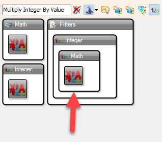

- Add "Multiply Integer By Value" component
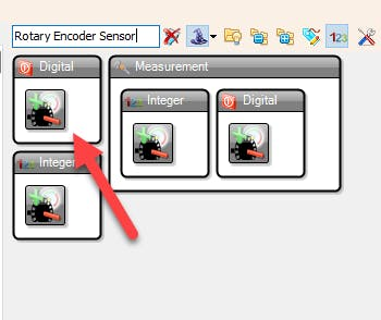
- Add "Rotary Encoder Sensor" component
- Add "Pulse Generator" component
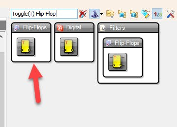
- Add "Toggle(T) Flip-Flop" component
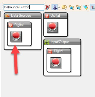
- Add "Debounce Button" component
1 / 3
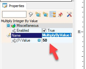
- Select "MultiplyByValue1" and in the Properties window set "Value" to 50
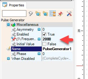
- Select "PulseGenerator1" and in the properties window set "Frequency" to 2000 << this will be the default starting speed of the stepper motor, you can adjust it to your needs
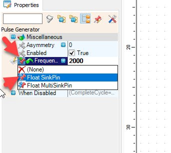
- select "Frequency" and click on the Pin icon and select "Float SinkPin"
1 / 3
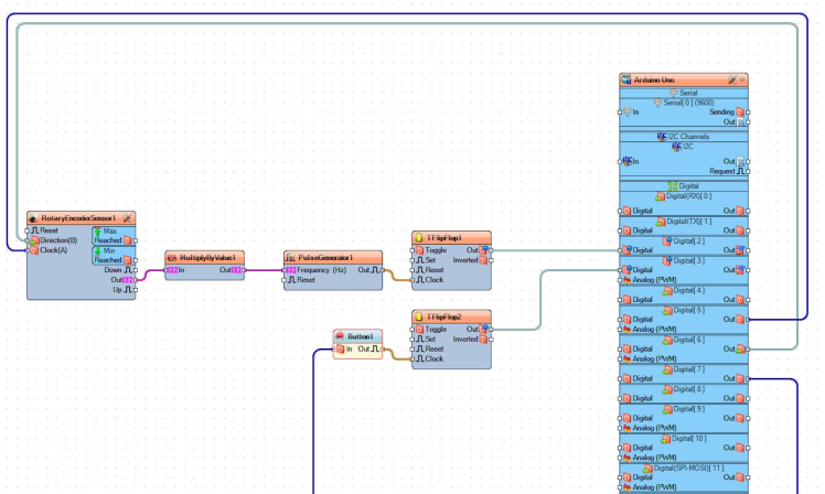
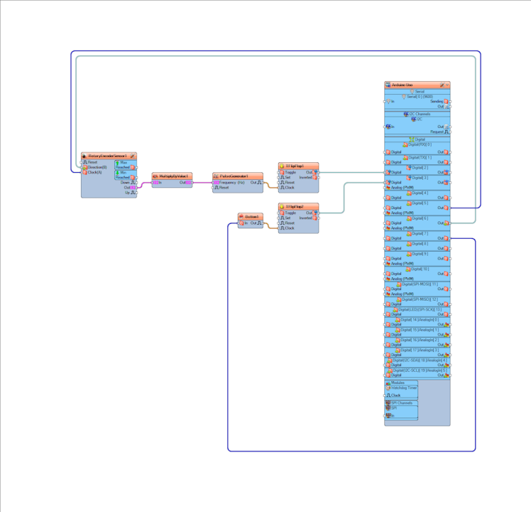
- Connect Arduino digital pin [6] to "RotaryEncoderSensor1" pin [Direction]
- Connect Arduino digital pin [5] to "RotaryEncoderSensor1" pin [Clock]
- Connect "RotaryEncoderSensor1" pin [Out] to "MultiplyByValue1" pin [In]
- Connect "MultiplyByValue1" pin [Out] to "PulseGenerator1" pin [In]
- Connect "PulseGenerator1" pin [Out] to "TFlipFlop1" pin [Clock]
- Connect "TFlipFlop1" pin [Out] to Arduino digital pin [2]
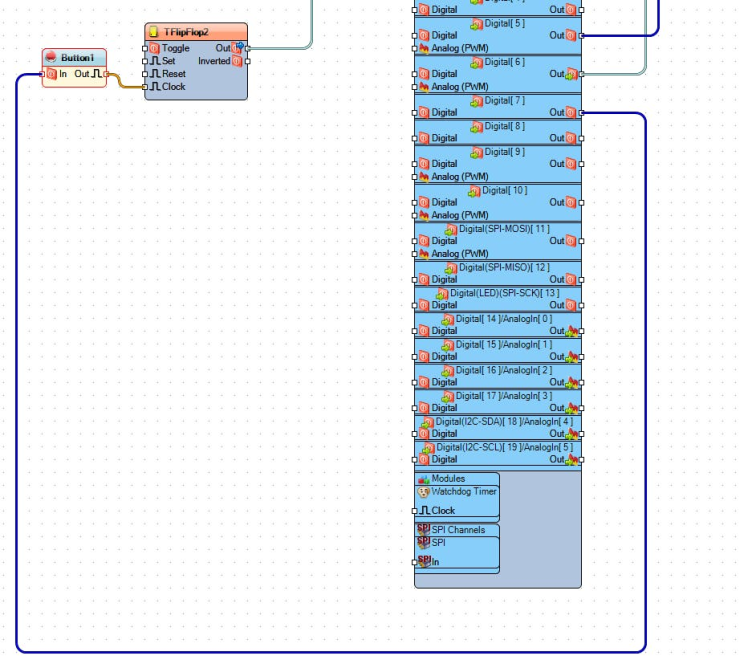
- Connect "Button1" pin [Out] to "TFlipFlop2" pin [Clock]
- Connect "TFlipFlop2" pin [Out] to Arduino digital pin [3]
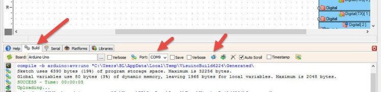
In Visuino, at the bottom click on the "Build" Tab, make sure the correct port is selected, then click on the "Compile/Build and Upload" button.
Step 9: PlayIf you power the Arduino module the motor will do will start to run and if you rotate the Encoder module the speed of the motor will change and if you press a button on the Encoder module the motor will change the direction.
Congratulations! You have completed your project with Visuino. Also attached is the Visuino project, that I created for this Tutorial, you can download it here and open it in Visuino: https://www.visuino.eu
Schematics, diagrams and documents
Code
Credits
Related products


Leave your feedback...