
Make A Phone Call Using The Sim900 Gsm Shield & Visuino

Made by Ron / Communication / Home Automation / Security / Sensors / IoT
About the project
In this tutorial you will learn how to make a phone call using the SIM900 GSM Shield and Visuino.
Items used in this project
Hardware components

Story
With one button you will be able to start a call and end the call with the second button.
You will also learn how to use the "Serial Software" component in Visuino.
Watch the Video!
Step 1: What You Will Need1 / 7
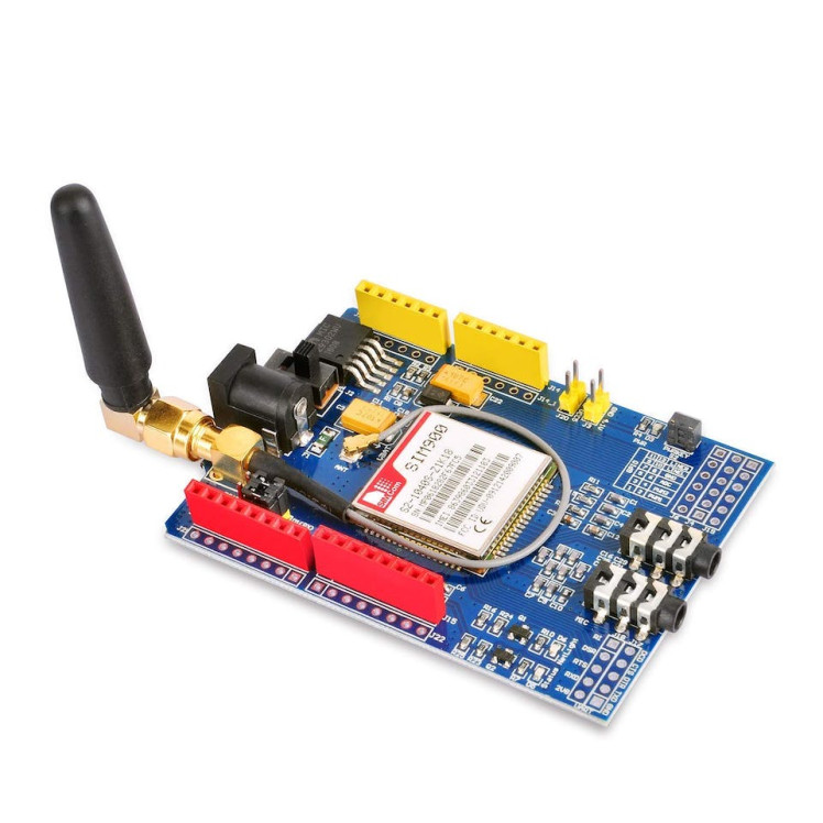
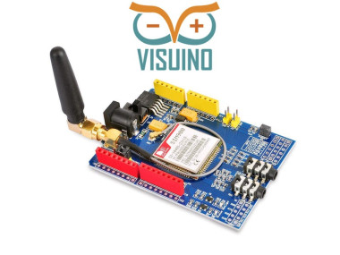
- SIM900 GSM Shield
- Sim card (You should disable the pin request on the sim card before using it with the GSM shield)
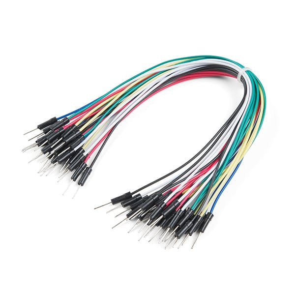
- Breadboard
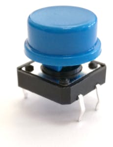
- 2X button
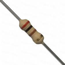
- 2X 1Kohm resistor
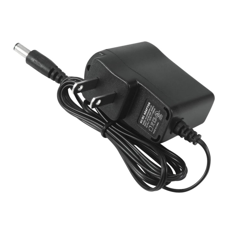
- 5V power supply with enough amps for the shield
- Visuino program: Download Visuino
1 / 3
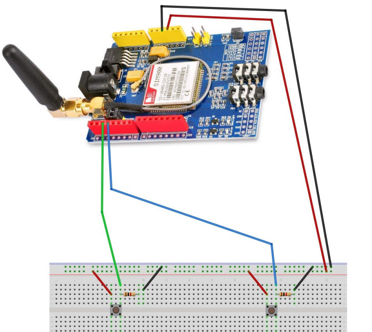
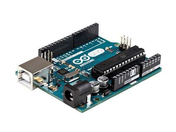
- Connect the SIM900 GSM Shield to the Arduino
- Connect Arduino pin [5V] to breadboard positive pin [Red line]
- Connect Arduino pin [GND] to breadboard negative pin [Black line]
- Connect Arduino Digital pin [2] to button1 on the breadboard and to the Resistor1
- Connect other side of the resistor1 to the breadboard pin [GND]
- Connect Other pin of the button1 to the breadboard positive pin [5V]
- Connect Arduino Digital pin [2] to button1 on the breadboard and to the Resistor1
- Connect other side of the resistor1 to the breadboard pin [GND]
- Connect Other pin of the button1 to the breadboard positive pin [5V]
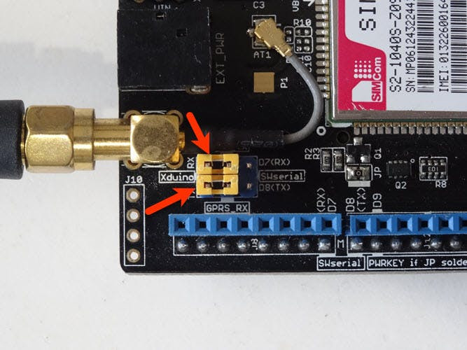
- Connect with the Jumpers on the shield pins D8(RX) & D7(TX) like you see it on the picture
- Make sure that the antenna is connected to the shield
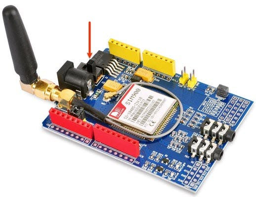
- Connect the 5V Power Supply to the shield, and set the switch on the shield to the External Power (See the picture)
- Once the Power is connected hold the Power button for 2s
- Once the connection with the Network is established the LED will blink every 3s
1 / 2
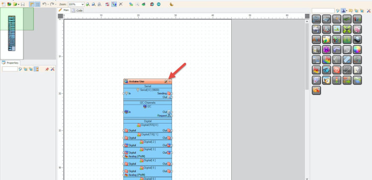
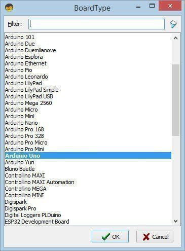
Start Visuino as shown in the first picture Click on the "Tools" button on the Arduino component (Picture 1) in Visuino When the dialog appears, select "Arduino UNO" as shown on Picture 2
Step 4: In Visuino Add Components1 / 3
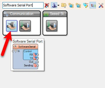
- Add "Software Serial Port" component
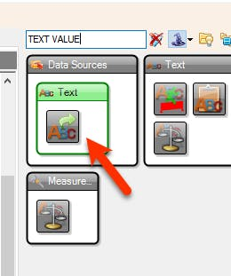
- Add "Add "Text Value" component
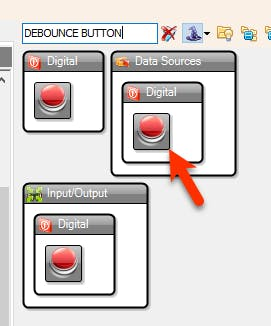
- Add 2X "Debounce Button" component
1 / 3
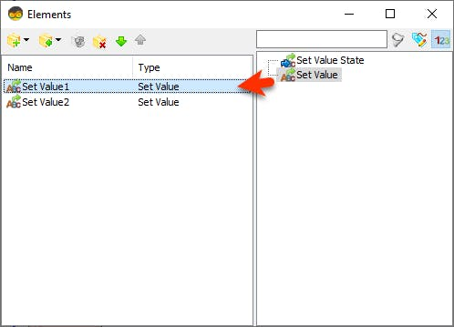
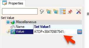

- Double click on the "TextValue1" and in the Elements window drag "Set Value" to the left side and in the properties window set "Value" to ATDP+ PHONE_NUMBER (International Format) & add semicolon at the end
Example: ATDP+38470987541;
- In the Elements window Drag another "Set Value" to the left side and in the properties window set "Value" to ATH
Example: ATH
- Close the Elements window
1 / 2
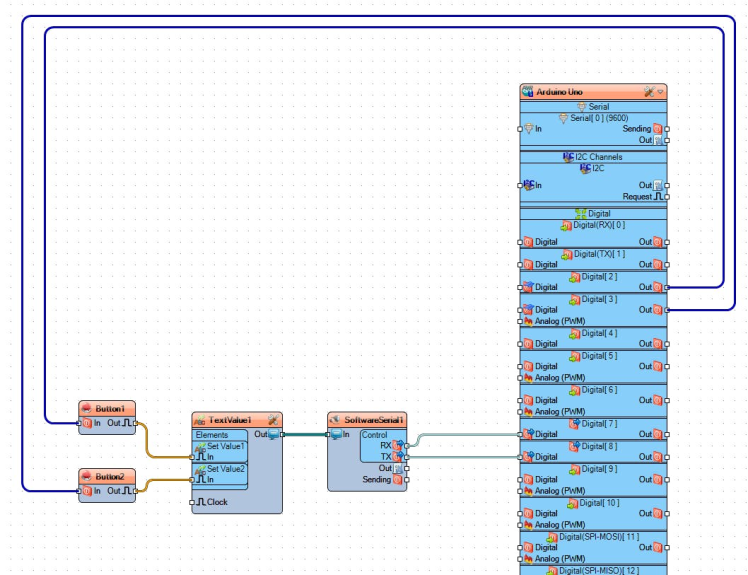
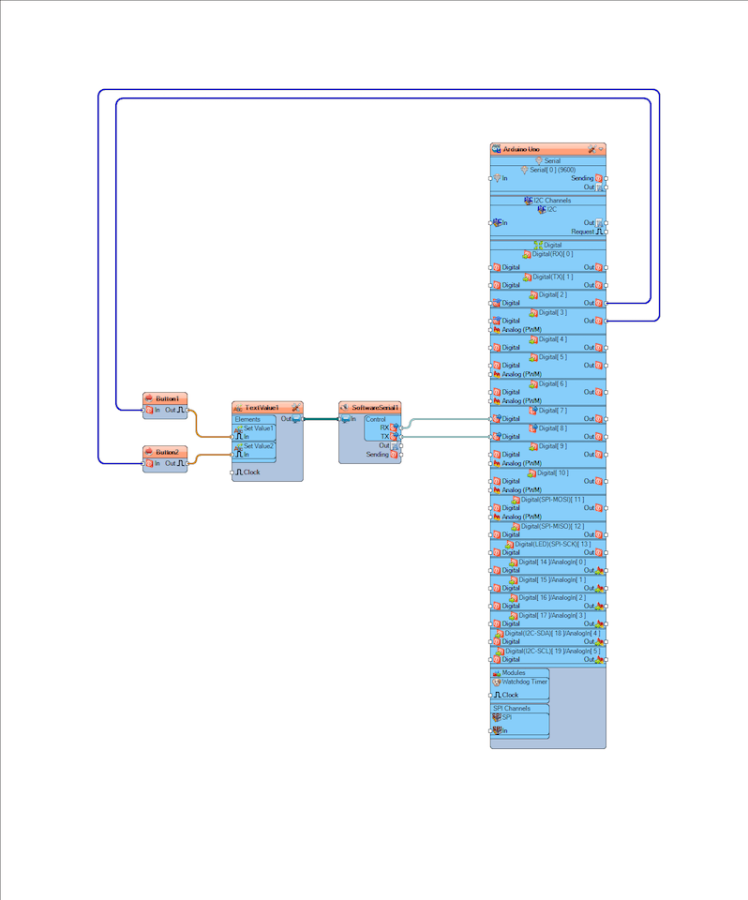
- Connect Arduino digital pin [2] to "Button1" pin [In]
- Connect Arduino digital pin [3] to "Button2" pin [In]
- Connect "Button1" pin [Out] to "TextValue1" > "Set Value1" pin [In]
- Connect "Button2" pin [Out] to "TextValue1" > "Set Value2" pin [In]
- Connect "TextValue1" pin [Out] to "SoftwareSerial1" pin [In]
- Connect "SoftwareSerial1" pin [RX] to Arduino Digital pin [7]
- Connect "SoftwareSerial1" pin [TX] to Arduino Digital pin [8]
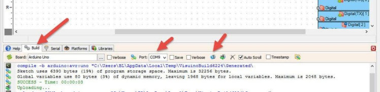
In Visuino, at the bottom click on the "Build" Tab, make sure the correct port is selected, then click on the "Compile/Build and Upload" button.
Step 8: PlayWhen you power the Shield wait a bit for the connection with the network to be established, once the connection is established the LED on the shield will blink every 3s.
Now you can press a button and you will make a call. To end the call just press the other button.
Congratulations! You have completed your GSM project with Visuino. Also attached is the Visuino project, that I created for this Tutorial. You can download and open it in Visuino: https://www.visuino.eu
Step 9: Using the Serial Window to Send Commands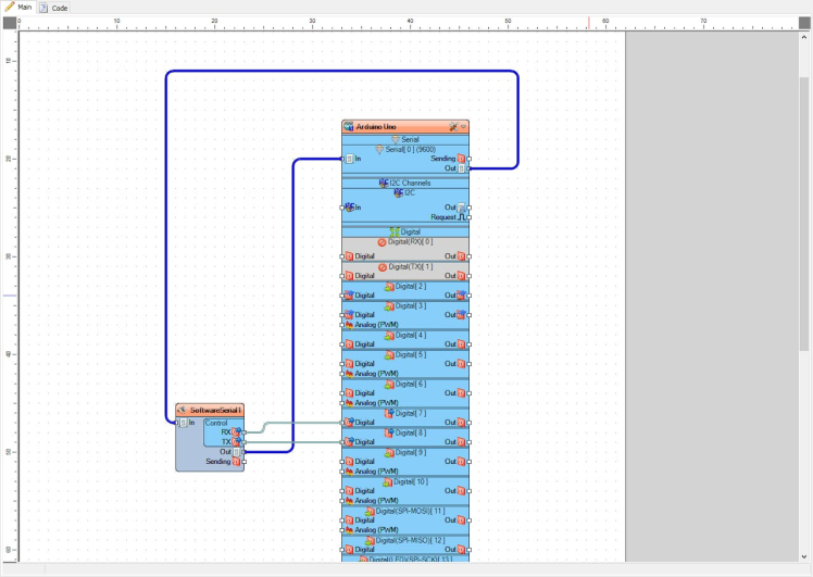
- Add "Software Serial Port" component
- Connect Arduino Serial pin [Out] to "SoftwareSerial1" pin [In]
- Connect "SoftwareSerial1" pin [RX] to Arduino Digital pin [7]
- Connect "SoftwareSerial1" pin [TX] to Arduino Digital pin [8]
- Connect "SoftwareSerial1" pin [Out] to Arduino Serial pin [In]
Upload the project (see the step Generate, Compile, And Upload The Arduino Code) and in Visuino select "Serial" tab, select the Port and click "Connect" button.
- Once connected you can start sending the commands to the module by typing for example: AT;
- This will ask the GSM Shield for the current status
Also attached is the Visuino project
Step 10: Troubleshooting- Supplying the SIM900 shield with enough power is very important, if it will not get enough power it might turn off
- AT command must have a semicolon at the end or it might return the message "NO CARRIER"
- Some mobile operators might block the GSM modules, in that case contact your mobile operator and ask for more information.
Schematics, diagrams and documents
Code
Credits
Related products


Leave your feedback...