
How To Make Arduino Obstacle Avoiding Robot Car With Radar

Made by Ron / Astronomy / Automotive / Environmental Sensing / Robotics / Sensors
About the project
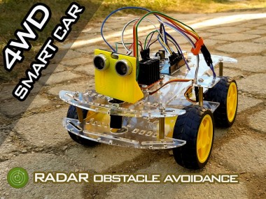
In this tutorial we are going to make an Arduino Obstacle Avoiding Robot Car with Radar using the HC-SR04 ultrasonic sensor &servo motor.
Items used in this project
Hardware components

Story
In this tutorial we are going to make an Arduino Obstacle Avoiding Robot Car with Radar using the HC-SR04 ultrasonic sensor attached to the servo motor.
Why is this project better than all the other "Obstacle Avoiding Car" projects out there, because most Projects out there only detects the Obstacle in the front and the then servo checks on the left or the right and decides where the Robot should go, so no real time detection on all angles.
On this Robot Car the servo rotates the ultrasonic all the time from the left side to the right side just like a radar does it, and as soon as the Obstacle is detected on any point the reverse direction is triggered and the direction of the travel is changed.
The Angle of the "Radar" detection can be adjusted and the distance of the detection can be adjusted as well.
Step 1: What You Will Need
1 / 6
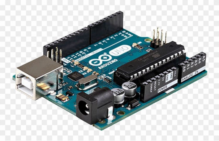

- Arduino UNO (or any other board)
- Smart Car Chassis 4WD
- L298N DC MOTOR CONTROLER
- Ultrasonic sensor (HC- SR04)
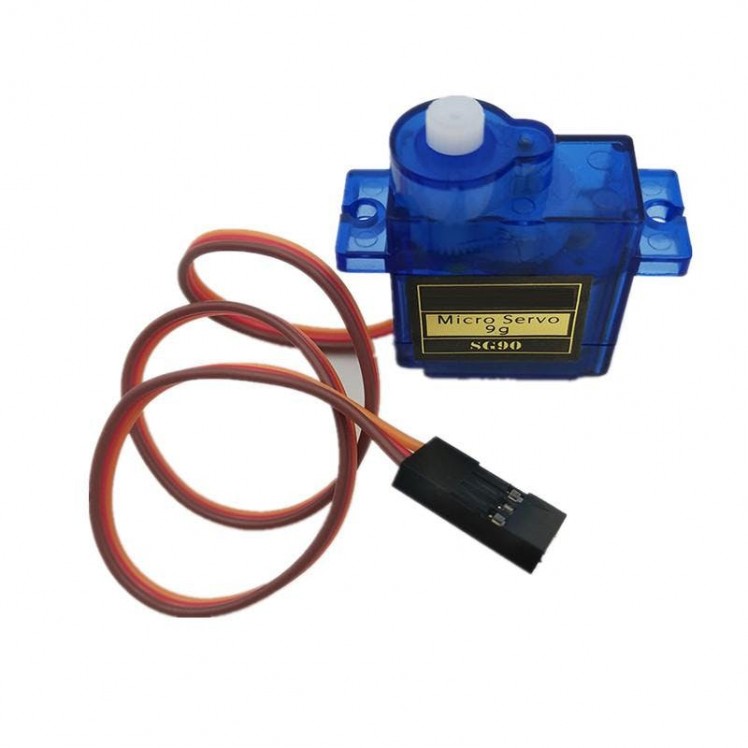
- Servo motor
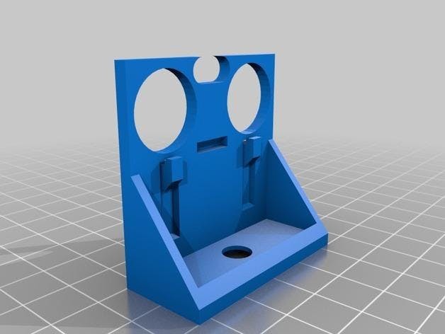
- Ultrasonic sensor (HC- SR04) bracket servo mounted - 3DPrinted part Download here If you do not have a bracket you can find some other way to attach the sensor to the servo motor, perhaps some glue, etc
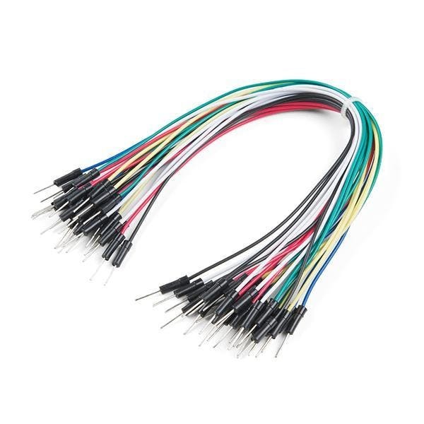
- Jumper wires
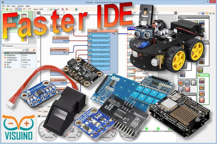
- Visuino program: Download Visuino
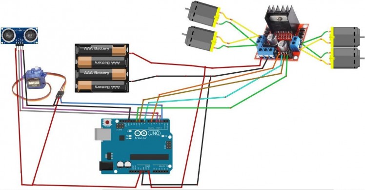
- Connect Power supply (batteries) pin (gnd) to motor driver controler pin (gnd)
- Connect Power supply (batteries) pin (+) to motor driver controler pin (+)
- Connect Power supply (batteries) pin (+) to Arduino pin (VIN)
- Connect GND from Arduino to motor driver controler pin (gnd)
- Connect digital pin(6) from Arduino to motor driver pin (IN1)
- Connect digital pin(8) from Arduino to motor driver pin (IN2)
- Connect digital pin(10) from Arduino to motor driver pin (IN3)
- Connect digital pin(11) from Arduino to motor driver pin (IN4)
- Connect DC motors (on the right side of the robot) to one side of motor driver
- Connect DC motor (on the left side of the robot) to other side of motor driver
- Connect Ultrasonic module pin (VCC) to Arduino pin [+5V]
- Connect Ultrasonic module pin (GND) to Arduino pin [GND]
- Connect Ultrasonic module pin (ECHO) to Arduino pin digital (4)
- Connect Ultrasonic module pin (TRIG) to Arduino pin digital (3)
- Connect Servo motor "Orange" (signal) pin to Arduino Digital pin[2]
- Connect Servo motor "Red" pin to Arduino positive pin[5V]
- Connect Servo motor "Brown" pin to Arduino negative pin[GND]
1 / 2
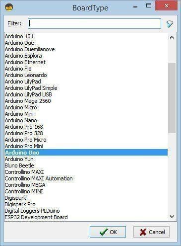
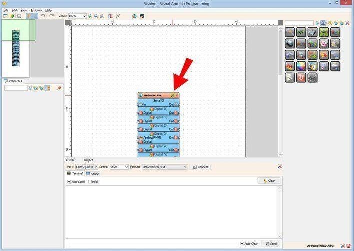
The Visuino: https://www.visuino.eu needs to be installed. Start Visuino as shown in the first picture Click on the "Tools" button on the Arduino component (Picture 1) in Visuino When the dialog appears, select "Arduino UNO" as shown on Picture 2
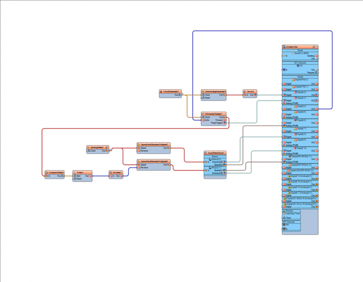
Step 4: In Visuino Add Components
1 / 10
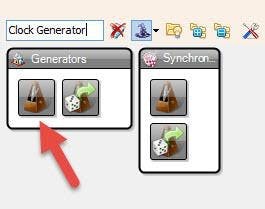
- Add "Clock Generator" component
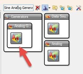
- Add "Sine Analog Generator"component
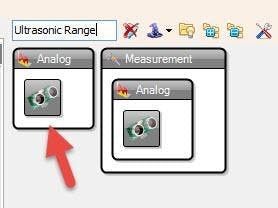
- Add "Ultrasonic Ranger" component
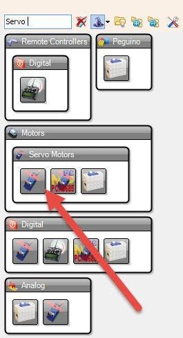
- Add "Servo" component
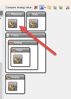
- Add "Compare Analog Value" component
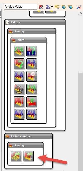
- Add "Analog Value" component
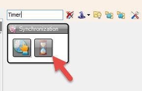
- Add "Timer" component
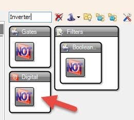
- Add "Inverter" component
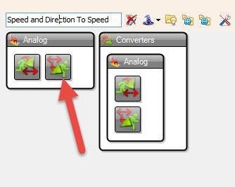
- Add 2X "Speed and Direction To Speed" component
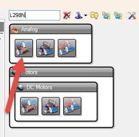
- Add "L298N" component
1 / 6
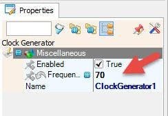
- Select "ClockGenerator1" and in the Properties window set "Frequency" to 70
This means how fas will the servo motor move (You can adjust the number)
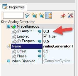
- Select "SineAnalogGenerator1" and in the Properties window set "Amplitude" to 0.3
This means ho far to the left or right the servo will rotate.(You can adjust the number)
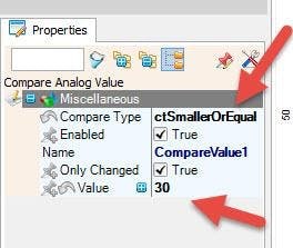
- Select "CompareValue1" and in the Properties window select "Compare Type" ctSmallerOrEqual and set "Value" to 30 (You can adjust the number)
This means that at the distance of 30cm or less the Robot car will reverse (You can adjust the number)
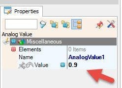
- Select "AnalogValue1" and in the Properties window set "Value" to 0.9
This will be the Default Speed of the Robot Car You can set it to less or to 1 to have a Full Speed
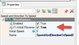
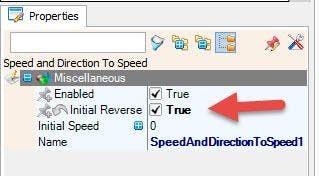
- Select "SpeedAndDirectionToSpeed1" and in the Properties window set "Initial Reverse" to True
This will reverse the Start Direction, Depending on your motor wiring, you can leave this to False
- Select "SpeedAndDirectionToSpeed2" and in the Properties window set "Initial Reverse" to True" This will reverse the Start Direction, Depending on your motor wiring, you can leave this to False
1 / 3
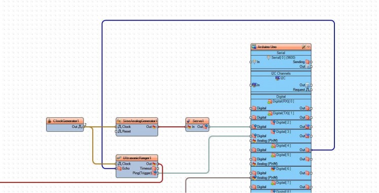
- Connect "ClockGenerator1" pin [Out] to "ClockGenerator1" pin [Clock]
- Connect "ClockGenerator1" pin [Out] to "SineAnalogGenerator1" pin [Clock]
- Connect "SineAnalogGenerator1" pin [Out] to "Servo1" pin [In]
- Connect "Servo1" pin[Out] to Arduino board digital pin [2]
- Connect Arduino board digital Out pin [4] to "UltrasonicRanger1" pin [Echo]
- Connect "UltrasonicRanger1" pin [Trigger] to Arduino board digital pin [3]
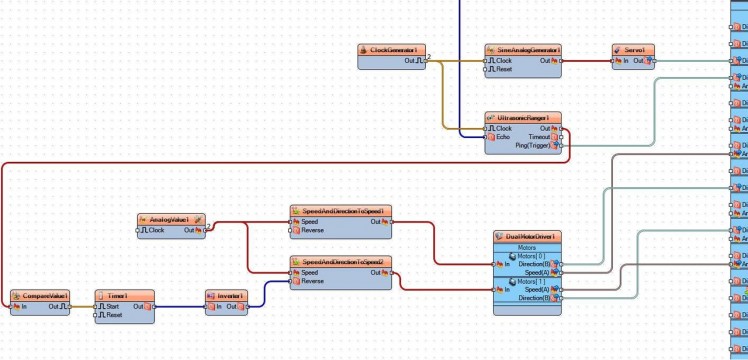
- Connect "UltrasonicRanger1" pin [Out] to "CompareValue1" pin [In]
- Connect "CompareValue1" pin [Out] to "Timer1" pin [Start]
- Connect "Timer1" pin [Out] to "Inverter1" pin [In]
- Connect "Inverter1" pin [Out] to "SpeedAndDirectionToSpeed2" pin [Reverse]
- Connect "IAnalogValue1" pin [Out] to "SpeedAndDirectionToSpeed1" pin [Speed]
- Connect "IAnalogValue1" pin [Out] to "SpeedAndDirectionToSpeed2" pin [Speed]
- Connect "SpeedAndDirectionToSpeed1" pin [Out] to "DualMotorDriver1" "Motor0" pin [In]
- Connect "SpeedAndDirectionToSpeed2" pin [Out] to "DualMotorDriver1" "Motor1" pin [In]
- Connect "DualMotorDriver1" "Motor0" pin [Direction B] to Arduino board digital pin [6]
- Connect "DualMotorDriver1" "Motor0" pin [Speed A] to Arduino board Analog(PWM) pin [8]
- Connect "DualMotorDriver1" "Motor1" pin [Speed A] to Arduino board Analog(PWM) pin [11]
- Connect "DualMotorDriver1" "Motor1" pin [Direction B] to Arduino board digital pin [10]

In Visuino, at the bottom click on the "Build" Tab, make sure the correct port is selected, then click on the "Compile/Build and Upload" button.
Step 8: PlayIf you power the Robot car & the Arduino module, the car wheels will start to spin and the servo motor will start to rotate the ultrasonic sensor. Once the sensor detects the obstacle the wheels will start to spin in reverse to avoid the obstacle.
Congratulations! You have completed your project with Visuino. Also attached is the Visuino project file, that I created for this Tutorial, you can download it and open it in Visuino: https://www.visuino.eu
Schematics, diagrams and documents
CAD, enclosures and custom parts
Code
Credits
Related products


Leave your feedback...