
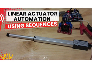
How To Automate Linear Actuator Using Sequence & Arduino

About the project
Learn how to automate Linear Actuator, how to set the speed and direction of movement, giving you complete automation control.
Project info
Difficulty: Easy
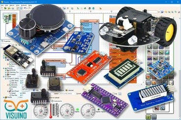
Platforms: Arduino, SparkFun, Visuino
Estimated time: 1 hour
License: GNU General Public License, version 3 or later (GPL3+)
Items used in this project
Hardware components

Software apps and online services
Story
In this step-by-step tutorial, you’ll discover how to create sequences that control your actuator with precise timing (in milliseconds or even microseconds). You’ll also see how to set the speed and direction of movement, giving you complete automation control. Perfect for beginners and advanced makers, this project shows just how easy it is to bring your actuator to life with Arduino + Visuino visual programming.
Step 1: What You Will Need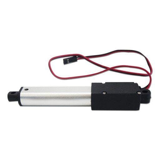
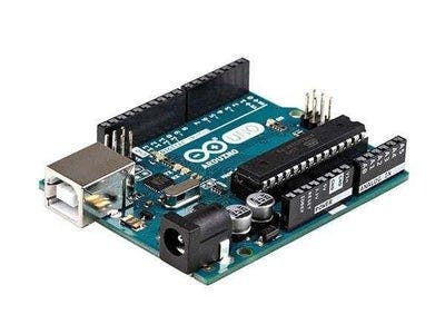
- Arduino UNO (Or any other Arduino)
- Linear Actuator
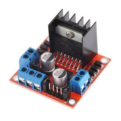
- LN298N DC Motor Driver
- Jumper wires
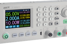
- Power Supply
- Visuino program: Download Visuino
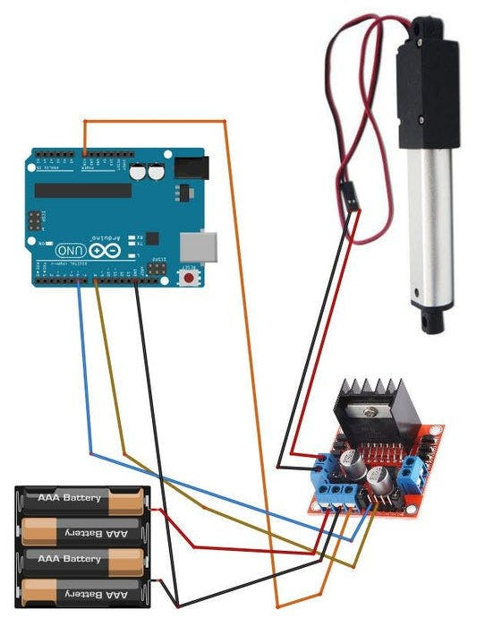
- Connect Power supply (batteries) pin (gnd) to motor driver controler pin (gnd)
- Connect Power supply (batteries) pin (+) to motor driver controler pin (+)
- Connect Power supply (batteries) pin (+) to Arduino pin (VIN)
- Connect GND from Arduino to motor driver controler pin (gnd)
- Connect digital pin(6) from Arduino to motor driver pin (IN1)
- Connect digital pin(8) from Arduino to motor driver pin (IN2)
- Connect Linear Actuator to the motor driver as you can see on the schematic
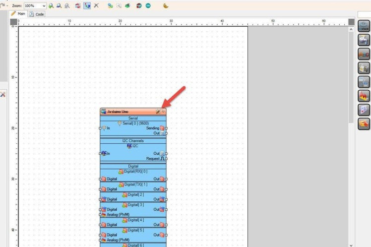
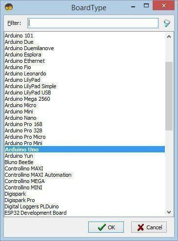
Start Visuino as shown in the first picture Click on the "Tools" button on the Arduino component (Picture 1) in Visuino When the dialog appears, select "Arduino UNO" as shown on Picture 2
Step 4: In Visuino Add Components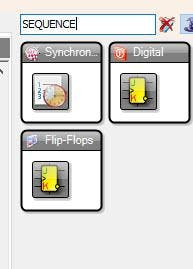

- Add "Sequence" component
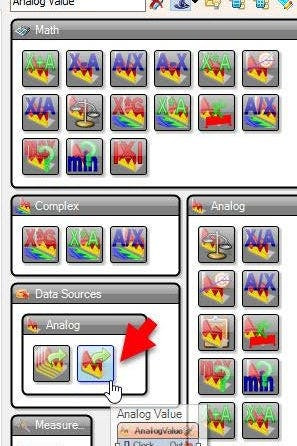
- Add "Analog Value" component
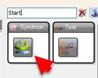
- Add "Start" component
- Add "Toggle(T) Flip-Flop" component
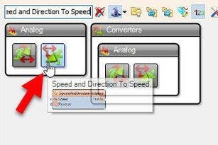
- Add "Speed and Direction To Speed" component
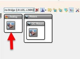
- Add "Dual DC Motor Driver Digital and PWM Pins Bridge (L9110S, L298N)" component
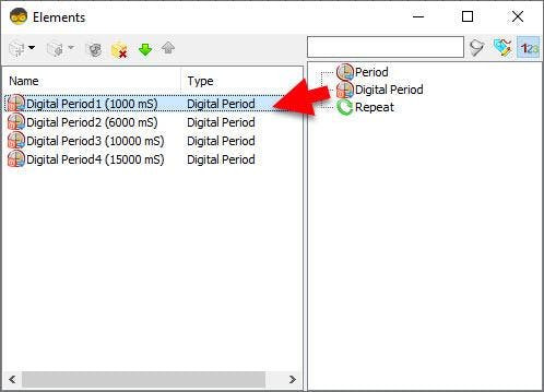
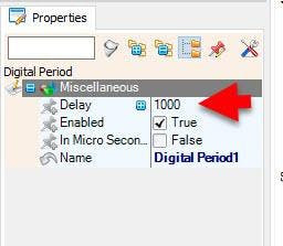
Double click on the "Sequence1" and in the Elements window drag to the left as many "Digital period" elements as you like, in this example we will add 4 "Digital period" elements and for each we will set the Delay in the properties window:
- Digital Period1: 1000
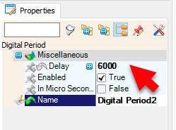
- Digital Period2: 6000
- Digital Period3: 10000
- Digital Period4: 15000
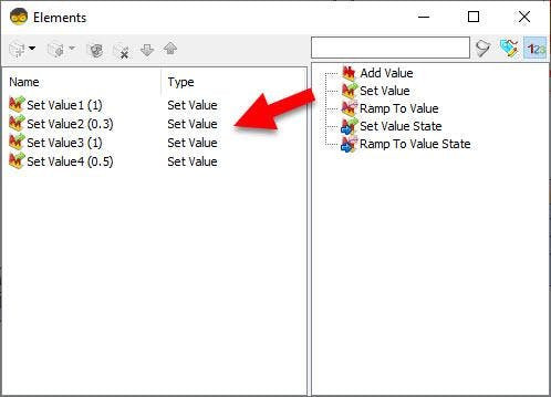
Double click on the "AnalogValue1" and in the Elements window drag to the left as many "Set Value" elements as you like, in this example we will add 4 "Set Value" elements and for each we will set the Value in the properties window:
- Set Value1: 1000
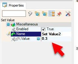
- Set Value2: 6000
- Set Value3: 10000
- Set Value4: 15000
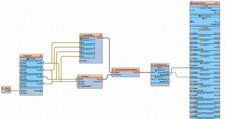
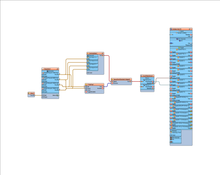
- Connect "Start1" pin [Out] to "Sequence1" pin [Start]
- Connect "Sequence1" > "DigitalPeriod1" pin [Out] to "AnalogValue1" > "Set Value1" pin [In]
- Connect "Sequence1" > "DigitalPeriod1" pin [Out] to "TFlipFlop1" pin [Set]
- Connect "Sequence1" > "DigitalPeriod2" pin [Out] to "AnalogValue1" > "Set Value2" pin [In]
- Connect "Sequence1" > "DigitalPeriod2" pin [Out] to "TFlipFlop1" pin [Reset]
- Connect "Sequence1" > "DigitalPeriod3" pin [Out] to "AnalogValue1" > "Set Value3" pin [In]
- Connect "Sequence1" > "DigitalPeriod3" pin [Out] to "TFlipFlop1" pin [Set]
- Connect "Sequence1" > "DigitalPeriod4" pin [Out] to "AnalogValue1" > "Set Value4" pin [In]
- Connect "Sequence1" > "DigitalPeriod4" pin [Out] to "TFlipFlop1" pin [Reset]
- Connect "AnalogValue1" pin [Out] to "SpeedAndDirectionToSpeed1" pin [Speed]
- Connect "TFlipFlop1" pin [Out] to "SpeedAndDirectionToSpeed1" pin [Reverse]
- Connect "SpeedAndDirectionToSpeed1" pin [Out] to "DualMotorDriver1" > [Motors.Item[0] pin [In]
- Connect "DualMotorDriver1" > [Motors.Item[0].Direction] pin [Out] to "Arduino" pin Digital pin [8]
- Connect "DualMotorDriver1" > [Motors.Item[0].Speed] pin [Out] to "Arduino" pin Digital > Analog PWM pin [6]
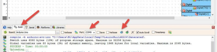
In Visuino, at the bottom click on the "Build" Tab, make sure the correct port is selected, then click on the "Compile/Build and Upload" button.
Step 8: PlayIf you power the Arduino module and the Linear Actuator will start to move according to your settings..
Congratulations! You have completed your project with Visuino. Also attached is the Visuino project, that I created for this tutorial, you can download it here and open it in Visuino: https://www.visuino.eu
Schematics, diagrams and documents
Code
Credits
Related products


Leave your feedback...