
Diy Garage Door Opener Using Arduino: A Beginner's Guide
Made by Elecrow / Games & Gaming / Home Automation / Lights / Robotics / Vehicles / IoT
About the project
In this article, we'll delve into the exciting realm of simulating a garage door opener using Arduino.
Project info
Difficulty: Easy
Estimated time: 2 hours
License: GNU General Public License, version 3 or later (GPL3+)
Items used in this project
Hardware components

Story
DIY Garage Door Opener Using Arduino: A Beginner's Guide
Embarking on the journey of learning Arduino opens up a world of possibilities for enthusiasts to create innovative projects. In this article, we'll delve into the exciting realm of simulating a garage door opener using Arduino. By following these steps, you'll not only gain a better understanding of Arduino modules but also have a functional garage door opener of your own.
Materials:
To begin this project, you'll need the following materials:
Jumper Wiresx60
Stick x1

Step 1: Understanding the SG-90 Servo Motor
The SG-90 Servohas 3 wires, with two of them being VCC and GND for power, while the third wire is for the signal input. The control signal for the servo operates on pulse width modulation (PWM) with a period of 20ms. The pulse width ranges from 0.5ms to 2.5ms, corresponding to a rudder position of 0 to 180 degrees. Essentially, providing the servo with a specific pulse width will maintain its output axis at a corresponding angle, regardless of external torque, until it receives a pulse signal of a different width to adjust to a new position.

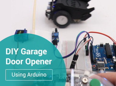
Step 2: Connecting the Components
When connecting the components, ensure that you correctly identify the positive and negative terminals to avoid damaging the components. You can choose the ports for connecting the servo and the infrared (IR) sensor according to your preference, but ensure that the servo is connected to a port capable of generating PWM signals.

Step 3: Writing the Code
Controlling the servo using Arduino is simplified by utilizing the "Servo.h" library. Include this library in your Arduino program to easily control the servo motor.
Go to my Githubfor code.

Step 4: Observing the Effect
After uploading the code to your Arduino board, adjust the trigger distance of the IR sensor manually to ensure it detects the proximity of passing objects, such as a car. Proper calibration ensures that the IR sensor triggers the servo motor to actuate the garage door opener mechanism.

Step 5: Subsequent Improvements
If you're familiar with interrupt functions, you'll likely recognize areas where my program could be enhanced for better robustness. If you haven't explored interrupts yet, I strongly advise delving into them. Once you've grasped their concepts, assisting me in optimizing this code should be a straightforward task for you.
Conclusion:
By following these steps, you've successfully created a DIY garage door opener using Arduino. This project not only serves as a practical application but also enhances your understanding of Arduino programming and hardware integration. Experiment with additional features and optimizations to further enhance the functionality of your garage door opener. Happy tinkering!
Code
Credits
Related products


Leave your feedback...