Bme280 Temperature, Humidity And Pressure On Nextion Display
About the project
Arduino Nano and Visuino: Plot BME280 Temperature, Humidity and Pressure on Nextion Display Scope - Quick and Easy
Items used in this project
Hardware components
Software apps and online services
Story
There are many Display options for adding graphical user interface to Arduino boards. Most of them however require considerable amount of memory, and processing time, and are not suitable for Arduino boards with limited memory, and processing power such as Arduino UNO or Arduino Nano. When the memory is limited, and an advanced user interface is needed, the Smart Programmable Serial Nextion Displays are a popular choice. The Itead offers a free Graphical Nextion Editor for designing the user interface of the display.
BME280 is a very accurate combined Temperature, Humidity, and Barometric Pressure sensor. It can be connected with I2C or SPI interface,
Visuino has full Nextion Display support, and I have been planning a tutorial for the Nextion support for a while. I also wanted to make tutorial for the BME280 sensor. Finally I decided to combine them, and make single tutorial displaying Temperature, Humidity, and Barometric Pressure from the BME280 on the 3 channels of a Scope(Waveform) component on the Nextion Display.
Step 1: Components

- One Arduino compatible board (I use Arduino Nano, because I have one, but any other will be just fine)
- One Nextion Serial Interface Smart Display (I used NX4024K032_11 but any other should also work)
- 4 Female-Female jumper wires
- To program the display you will also need a 5V USB to TTL Serial Converter Module
1 / 3 • Picture 1
Picture 1
Picture 2
Picture 3
To program the Nextion Display with the Nextion Editor you need to connect it with a USB to TTL Serial Converter to your computer:
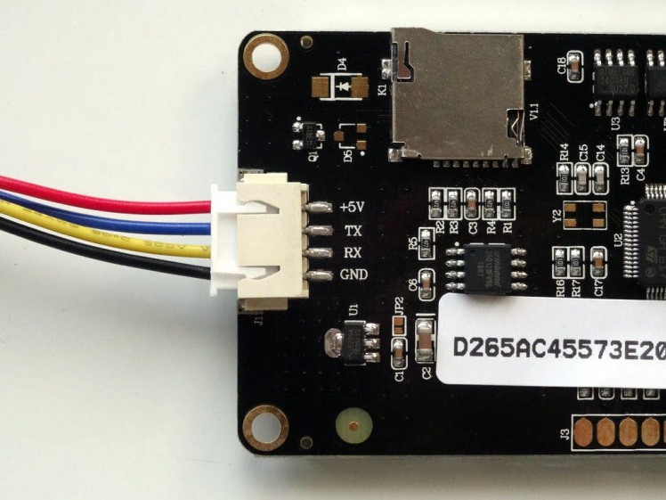
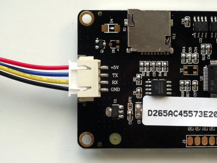
- Connect the Nextion Wires Connector to the Display (Picture 1)
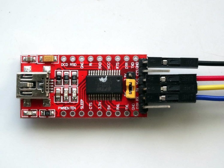
- If your USB to Serial Module is configurable, make sure it is set to provide 5V power (Picture 2) (In my case I needed to configure it with a power selection jumper)
- Connect the Ground Wire (Black wire) from the Nextion Display to the Ground pin of the USB to TTL Serial Converter Module (Picture 2)
- Connect the Power (+5V) Wire (Red wire) from the Nextion Display to the Power(VCC/+5V) pin of the USB to TTL Serial Converter Module (Picture 2)
- Connect the RX Wire (Yellow wire) from the Nextion Display to the TX pin of the USB to TTL Serial Converter Module (Picture 2)
- Connect the TX Wire (Blue wire) from the Nextion Display to the RX pin of the USB to TTL Serial Converter Module (Picture 2)
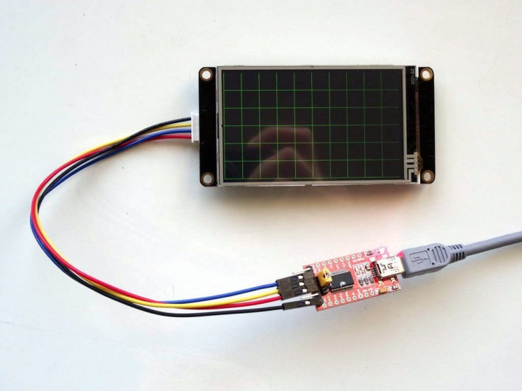
- Connect the USB to TTL Serial Converter Module to the computer with a USB cable (Picture 3)
1 / 4 • Picture 1
Picture 1
Picture 2
Picture 3
Picture 4
To program the Nextion Display, you will need to Download and Install the Nextion Editor.
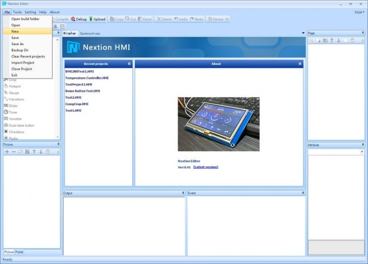
- Start the Nextion Editor (Picture 1)
- From the Menu select |FileNew| (Picture 1)
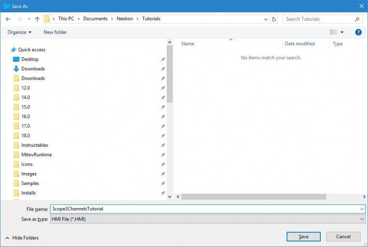
- In the "Save As" dialog, type project file name, and select a location to save the project (Picture 2)
- Click on the "Save" button (Picture 2)
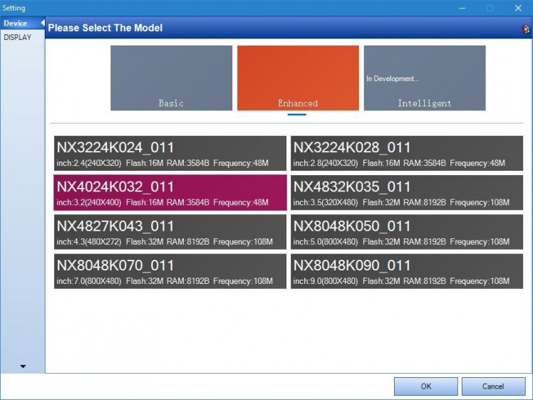
- In the "Settings" dialog, select the Display type (In my case NX4024K032_11) (Picture 3)
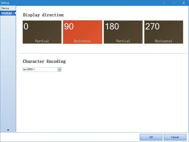
- Click on the "DISPLAY" tab on the left to show the Display settings (Picture 4)
- Select Horizontal orientation for the display (Picture 4)
- Click on the "OK" button to close the dialog (Picture 4)
1 / 4 • Picture 1
Picture 1
Picture 2
Picture 3
Picture 4
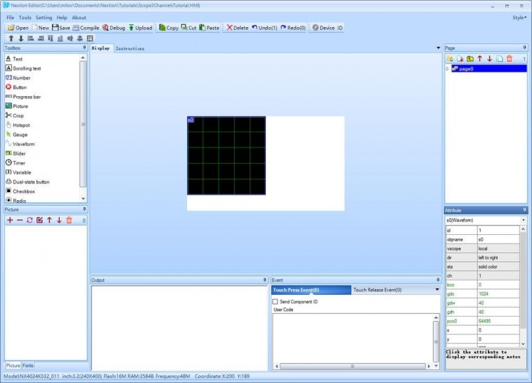
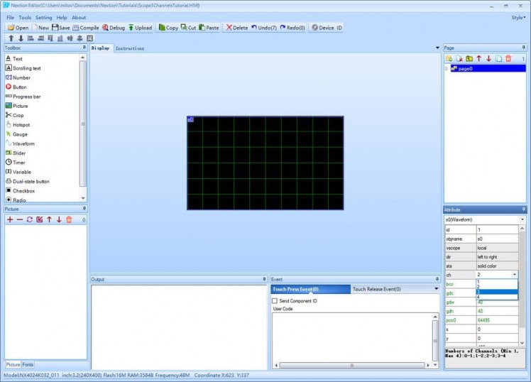
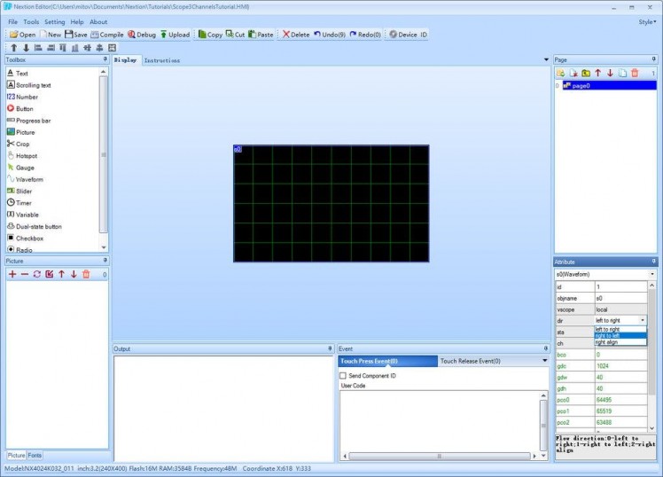
We need to add a Scope component, and configure it to have 3 channels for the Temperature, Pressure, and Humidity:
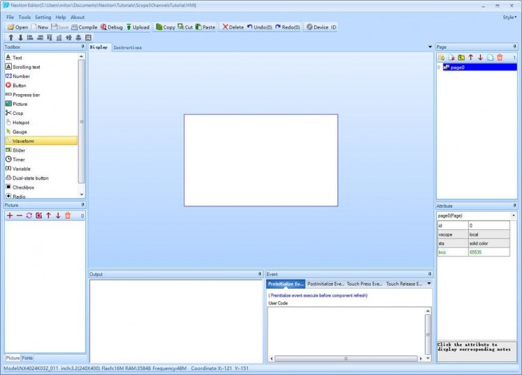
- In the "Toolbox" on the left click on the "Waveform" component (Picture 1) to add it to the design area (Picture 2)
- Resize the component to fill the display (Picture 3)
- In the "Attribute" toolbox, set the value of the "ch" attribute to "3" (Picture 3)
- In the "Attribute" toolbox, set the value of the "dir" attribute to "right to left" (Picture 4)
1 / 4 • Picture 1
Picture 1
Picture 2
Picture 3
Picture 4
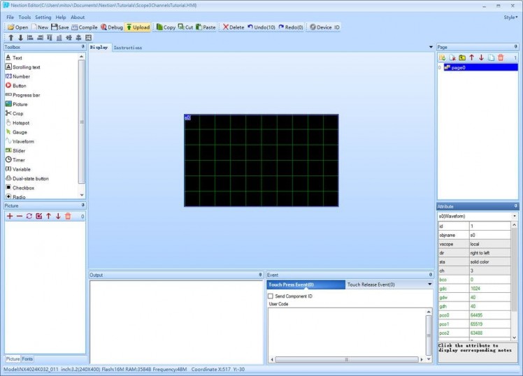
- Click on the "Upload" button (Picture 1)
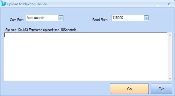
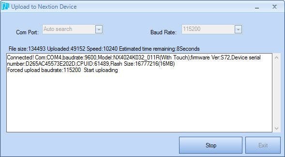
- In the "Upload to Nextion Device" dialog, click on the "Go" button (Picture 2) to start the upload (Picture 3)
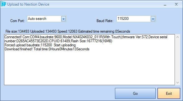
- When the upload finishes (Picture 4), click on the "Exit" button to close the dialog.
1 / 2 • Picture 1
Picture 1
Picture 2
Since the Arduino Nano has only one Serial port, and it is needed to program the Arduino, you will need to program the Arduino Nano before the Nextion Display is connected.
To start programming the Arduino, you will need to have the Arduino IDE installed from here: http://www.arduino.cc/ .
Please be aware that there are some critical bugs in Arduino IDE 1.6.6.
Make sure that you install 1.6.7 or higher, otherwise this Tutorial will not work!
The Visuino: https://www.visuino.com also needs to be installed.
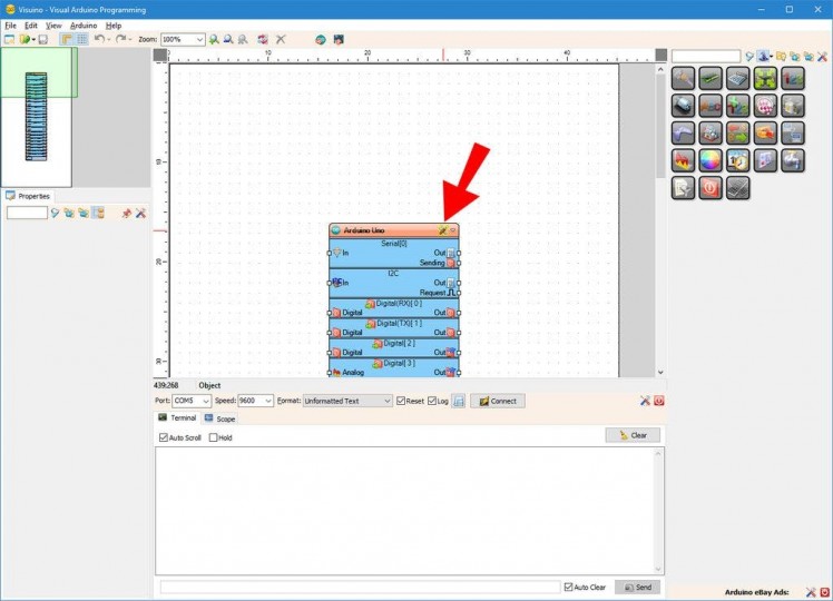
- Start Visuino as shown in the first picture
- Click on the "Tools" button on the Arduino component (Picture 1) in Visuino
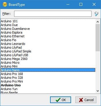
- When the dialog appears, select Arduino Nano as shown in Picture 2
1 / 3 • Picture 1
Picture 1
Picture 2
Picture 3
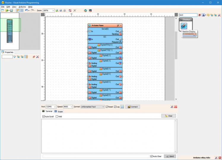
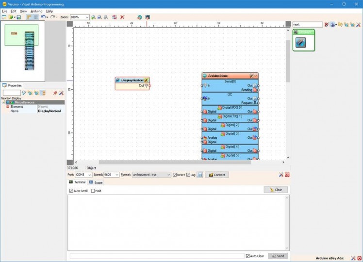
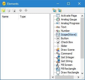
To control the Nextion Display, we need to add Nextion Display component in Visuino, and then add to it element to control the Scope:
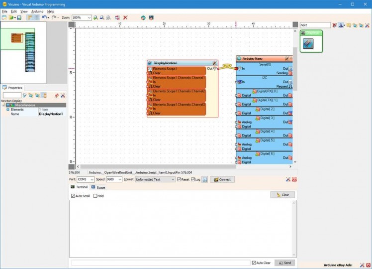
- Type "next" in the Filter box of the Component Toolbox then select the "Nextion Display" component (Picture 1), and drop it in the design area
- Click on the "Tools" button of the DisplayNextion1 component (Picture 2)
- In the "Elements" editor select the “Scope(Wave)” element, and then click on the "" button on the left (Picture 2) to add Scope element (Picture 3)
1 / 4 • Picture 1

Picture 1
Picture 2
Picture 3
Picture 4
Next we need to add channels to the Scope.
- In the Object Inspector, click on the "..." button next to the value of the "Channels" sub property of the Scope1 element (Picture 1)
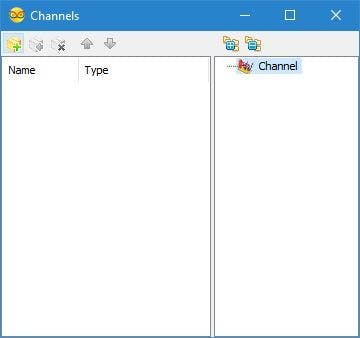
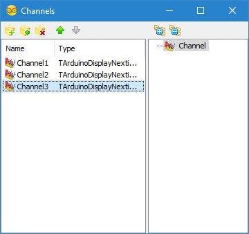
- In the Channels editor select “Channel” element on the right, and then click 3 times on the "" button on the left (Picture 2) to add 3 channels (Picture 3)
- Close the "Channels" and the Display "Elements" dialogs
- Connect the "Out" output pin of the DisplayNextion1 component to the to the "In" input pin of the "Serial[ 0 ]" channel of the Arduino component (Picture 4)
1 / 4 • Picture 1
Picture 1
Picture 2
Picture 3
Picture 4
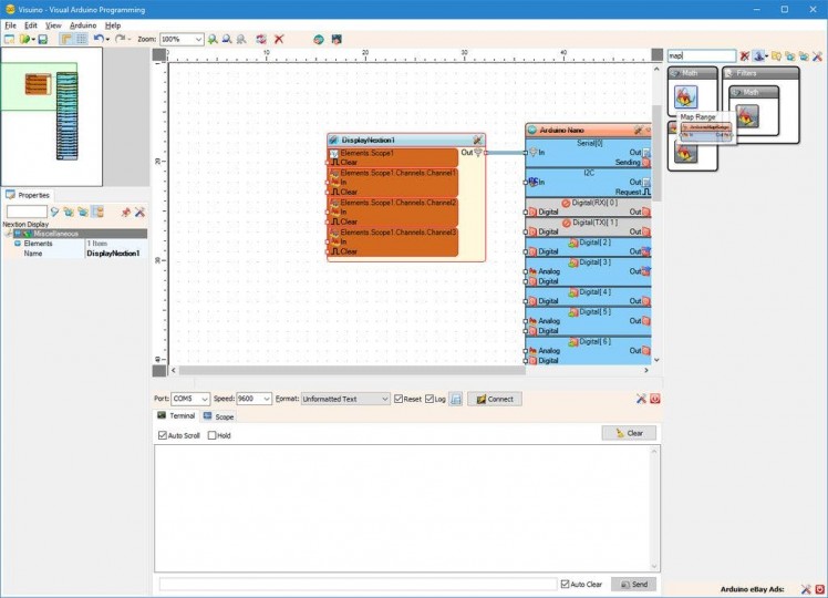
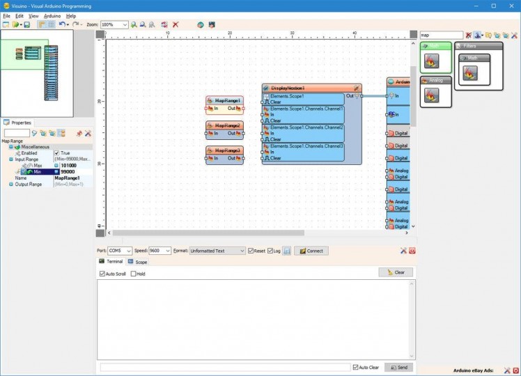
The Nextion Display Scope channels are designed to display values between 0.0 and 1.0 . To display the Temperature, Humidity, and Pressure, we need to convert the values to the 0.0 to 1.0 range. We can use Map Range components for this:
- Type "map" in the Filter box of the Component Toolbox then select the "Map Range" component (Picture 1), and drop 3 of them in the design area
- Select the MapRange1 component (Picture 2)
- In the Object Inspector expand the "Input Range" property (Picture 2)
- In the Object Inspector set the value of the "Max" subproperty of the "Input Range" property to "101000" (Picture 2) (You may need to set different value, if the air pressure ate your location is much different)
- In the Object Inspector set the value of the "Min" subproperty of the "Input Range" property to "99000" (Picture 2) (You may need to set different value, if the air pressure ate your location is much different)
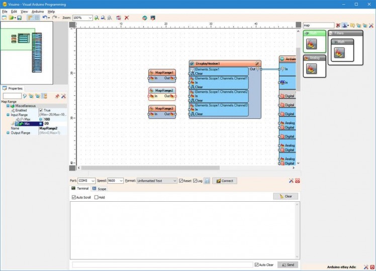
- Select the MapRange2 component (Picture 3)
- In the Object Inspector expand the "Input Range" property (Picture 3)
- In the Object Inspector set the value of the "Max" subproperty of the "Input Range" property to "100" (Picture 3)
- In the Object Inspector set the value of the "Min" subproperty of the "Input Range" property to "-20" (Picture 3)
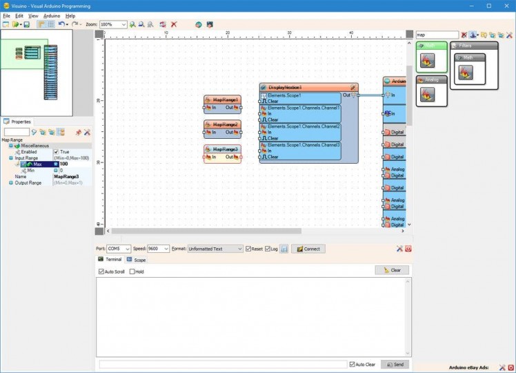
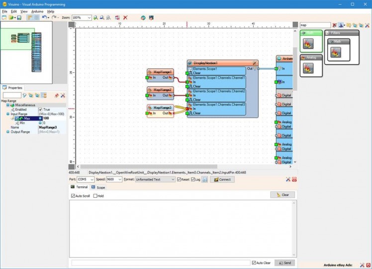
- Select the MapRange3 component (Picture 4)
- In the Object Inspector expand the "Input Range" property (Picture 4)
- In the Object Inspector set the value of the "Max" subproperty of the "Input Range" property to "100" (Picture 4)
1 / 3 • Picture 1
Picture 1

Picture 2
Picture 3
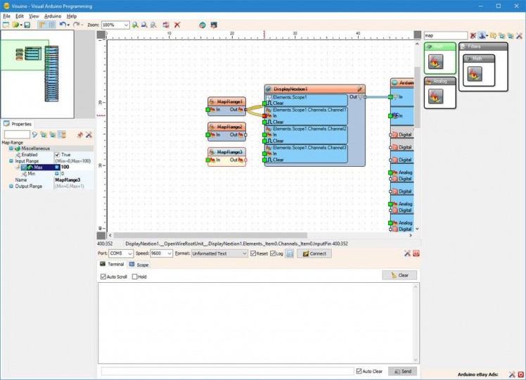
- Connect the "Out" output pin of the MapRange1 component to the "In" input pin of the "Elements.Scope1.Channels.Channel1" element of the DisplayNextion1 component (Picture 1)
- Connect the "Out" output pin of the MapRange2 component to the "In" input pin of the "Elements.Scope1.Channels.Channel2" element of the DisplayNextion1 component (Picture 2)
- Connect the "Out" output pin of the MapRange3 component to the "In" input pin of the "Elements.Scope1.Channels.Channel3" element of the DisplayNextion1 component (Picture 3)
1 / 5 • Picture 1
Picture 1
Picture 2
Picture 3
Picture 4

Picture 5
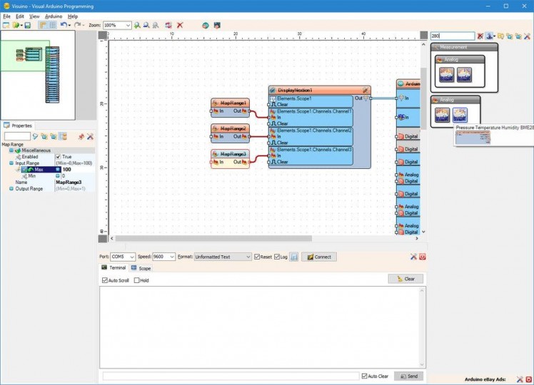
We need to add a component to read the data from the BME280 Module:
- Type "280" in the Filter box of the Component Toolbox then select the "Pressure Temperature Humidity BME280 I2C" component (Picture 1), and drop it in the design area
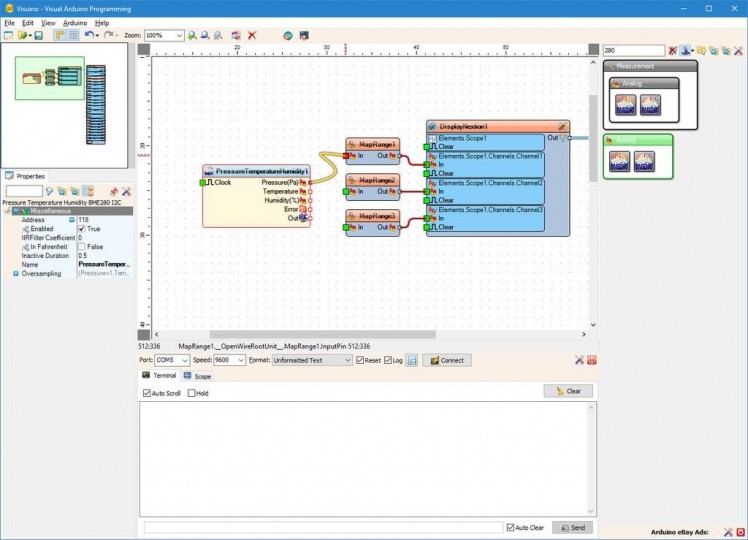
- My BME280 Module has I2C address of 118(0x76). If your modules has a different address, you will need to set the value of the "Address" property (Picture 2)
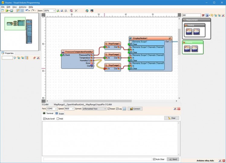
- Connect the "Pressure(Pa)" output pin of the PressureTemperatureHumidity1 component to the to the "In" pin of the MapRange1 component (Picture 2)
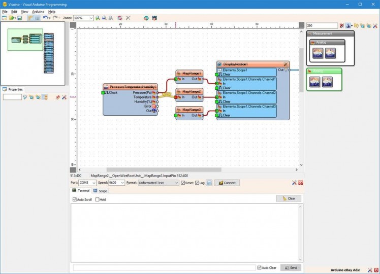
- Connect the "Temperature" output pin of the PressureTemperatureHumidity1 component to the to the "In" pin of the MapRange2 component (Picture 3)
- Connect the "Humidity(%)" output pin of the PressureTemperatureHumidity1 component to the to the "In" pin of the MapRange3 component (Picture 4)
- Connect the "Out" output pin of the PressureTemperatureHumidity1 component to the to the "In" pin of the I2C channel of the Arduino component (Picture 5)
1 / 3 • Picture 1
Picture 1

Picture 2
Picture 3
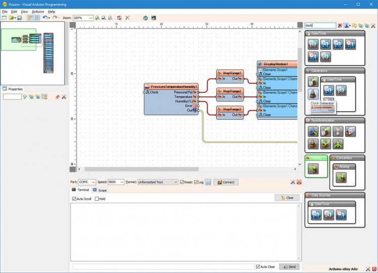
We can use the project as it is, however it will refresh the Scope very fast all the time. It is better if the Scope is updated as example 10 times a second. For this we will add a clock component to clock the reading from the sensor and the updating of the Scope.
- Type "clock" in the Filter box of the Component Toolbox then select the "Clock Generator" component (Picture 1), and drop it in the design area
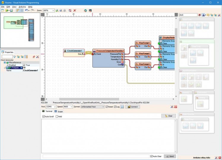
- In the Object Inspector, set the value of the "Frequency" property of the ClockGenerator1 to "10" (Picture 2)
- Connect the "Out" output pin of the ClockGenerator1 component to the "Clock" input pin of the PressureTemperatureHumidity1 component (Picture 3)
1 / 2 • Picture 1

Picture 1

Picture 2
- In Visuino, Press F9 or click on the button shown on Picture 1 to generate the Arduino code, and open the Arduino IDE
- In the Arduino IDE, click on the Upload button, to compile and upload the code (Picture 2)
1 / 3 • Picture 1
Picture 1

Picture 2
Picture 3
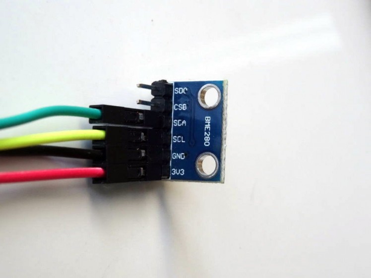
- Connect 3V3 VCC Power(Red wire), Ground(Black wire),SDA(Green wire), and SCL(Yellow wire), to the BME280 Module (Picture 1)
- Connect the other end of the Ground wire(Black wire) to Ground pin of the Arduino Nano board (Picture 2)
- Connect the other end of the 3V3 VCC Power wire(Red wire) to the 3V3 power pin of the Arduino Nano board (Picture 2)
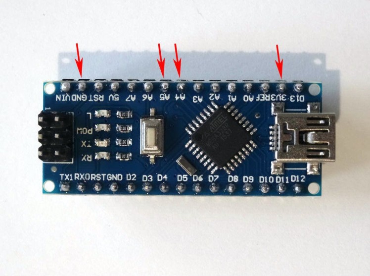
- Connect the other end of the SDA wire(Green wire) to SDA/Analog pin 4 of the Arduino Nano board (Picture 2)
- Connect the other end of the SCL wire(Yellow wire) to SCL/Analog pin 5 of the Arduino Nano board (Picture 2)
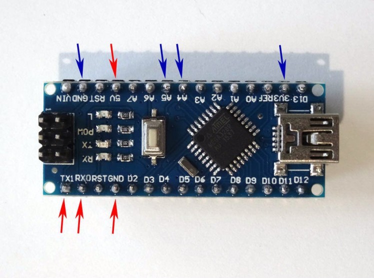
- Picture 3 shows where are the Ground, 3V3 Power, SDA/Analog pin 4, and SCL/Analog pin 5, pins of the Arduino Nano
1 / 4 • Picture 1
Picture 1
Picture 2
Picture 3
Picture 4
- Disconnect the Nextion Display wires from the USB to TTL Serial Converter Module
- Connect the Ground
- Disconnect the Nextion Display wires from the USB to TTL Serial Converter Module
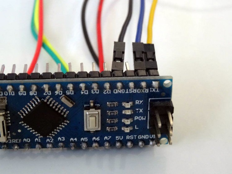
- Connect the Ground Wire (Black wire) from the Nextion Display to the Ground pin of the Arduino Nano (Picture 2)
- Connect the TX Wire (Blue wire) from the Nextion Display to the RX(D0) pin of the Arduino Nano (Picture 2)
- Connect the RX Wire (Yellow wire) from the Nextion Display to the TX(D1) pin of the Arduino Nano (Picture 2)
- Picture 4 shows where are the Ground, 5V Power, RX/Digital pin 0, and TX/Digital pin 1, pins of the Arduino Nano
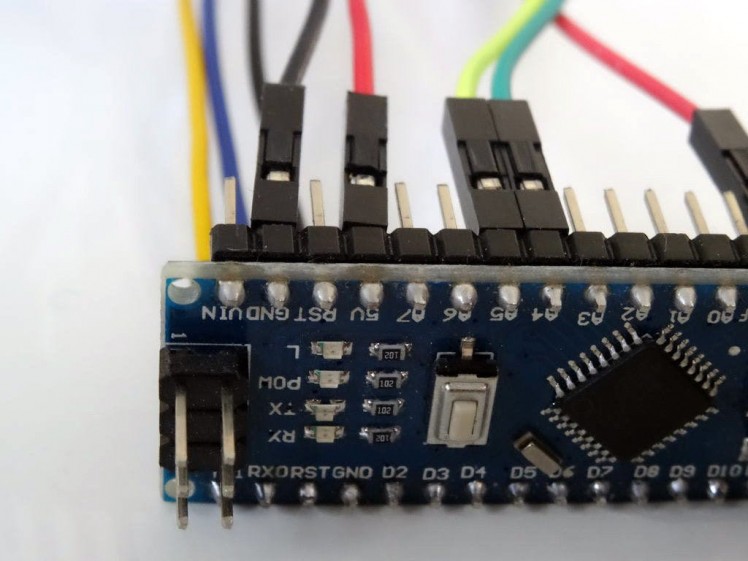
- Connect the +5V Power Wire (Red wire) from the Nextion Display to the 5V Power pin of the Arduino Nano (Picture 3)
- Picture 4 shows in Red where are the Ground, 5V Power, RX/Digital pin 0, and TX/Digital pin 1, pins of the Arduino Nano (In Blue are shown the pins connected in the previous step)
1 / 2 • Picture 1
Picture 1
Picture 2
Congratulations! You have completed the project.
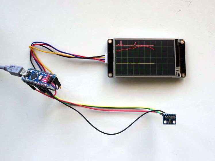
Picture 1 shows the connected and powered up project. As you can see on the picture, and in the Video the Scope on the Nextion Display will plot the Pressure, the Temperature, and the Humidity from the BME280 Module.
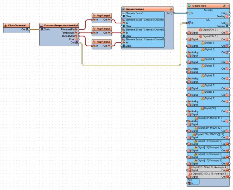
On Picture 2 you can see the complete Visuino diagram.
Attached is the Visuino project, that I created for this Tutorial. You can download and open it in Visuino: https://www.visuino.com
Also attached in the same zip is the Nextion Editor project for the Nextion Display.




Leave your feedback...