
Arduino How To Make A Smart Button

About the project
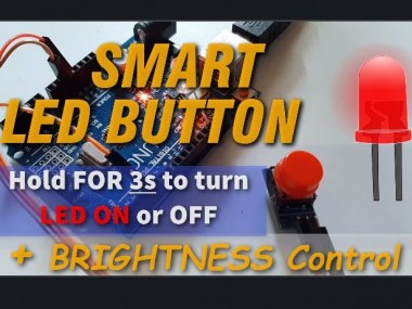
In this project we will learn how to Turn the LED ON or OFF by pressing a button for 3s and also we can change its brightness while its ON.
Items used in this project
Hardware components

Story
In this project we will learn how to Turn the LED ON or OFF by pressing a button for 3s and also while the LED is ON we can change its brightness. The goal of this tutorial is to show how easily you can control different things, all with just one button, this is something that we see in the modern media devices such as portable mp3 players, etc
Watch the Video!
Step 1: What You Will Need
1 / 5
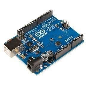

- Arduino UNO (or any other Arduino)
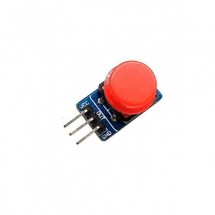
- Button module
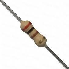
- 200 ohm resistor
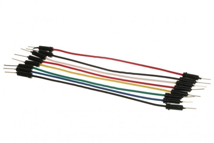
- Jumper wires
- LED
- Visuino program: Download Visuino
Step 2: The Circuit
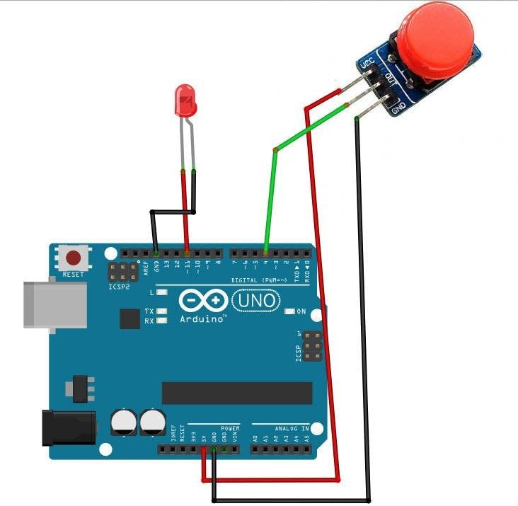
- Connect Button1 pin [VCC] to Arduino positive pin[5V]
- Connect Button1 pin [GND] to Arduino negative pin[GND]
- Connect Button1 signal pin [S] to Arduino digital pin[4]
- Connect LED positive pin [+] to 200 ohm resistor
- Connect other side of the 200 ohm resistor to Arduino digital pin[11]
- Connect LED negative pin [ - ] to Arduino negative pin[GND]
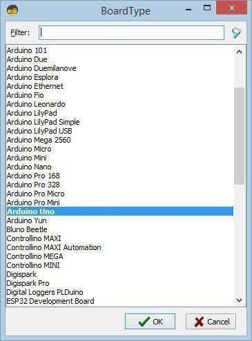
Step 3: Start Visuino, and Select the Arduino UNO Board Type
1 / 2
The Visuino: https://www.visuino.eu also needs to be installed. Download Free version or register for a Free Trial.
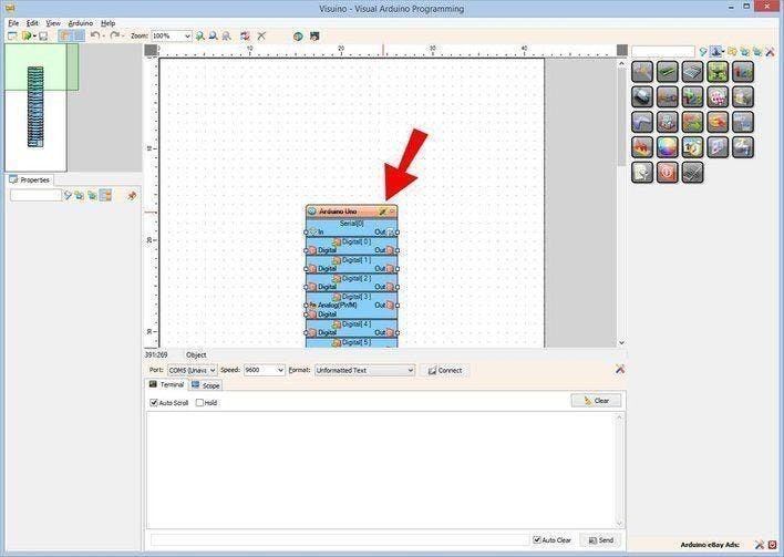
Start Visuino as shown in the first picture Click on the "Tools" button on the Arduino component (Picture 1) in Visuino When the dialog appears, select "Arduino UNO" as shown on Picture 2
Step 4: In Visuino Add
1 / 9
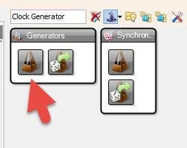
- Add "Clock generator" component
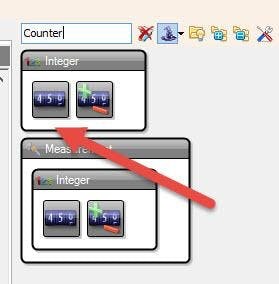
- Add 2X "Counter" component
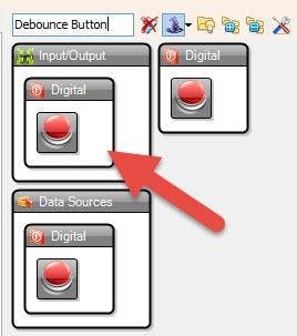
- Add "Debounce Button" component
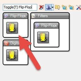
- Add "Toggle(T) Flip-Flop" component
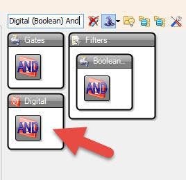
- Add "Digital (Boolean) And" component
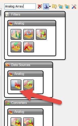
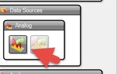
- Add "Analog Array" component
- Add "Analog Value" component
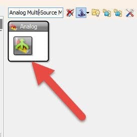
- Add "Analog Multi-Source Merger" component
Step 5: In Visuino Set Components
1 / 8
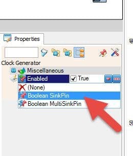
- Select "ClockGenerator1" and in the properties window select "Enabled" and click on the pin icon and select "Boolean SinkPin"
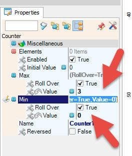
- Select "Counter1" and in the properties window set Max > Value to 3 << this is the time for ON/OFF
- and Min > Value to 0
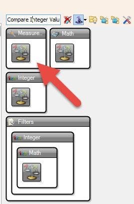
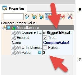
- Select "CompareValue1" and in the properties window set "Compare Type" to ctBiggerOrEqual
- and Value to 3 << this is the time for ON/OFF
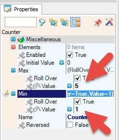
- Select "Counter2" and in the properties window set Max > Value to 5 << this is used for number of brightness steps
- and Min > Value to 1
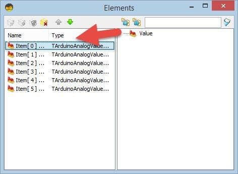
- Double click on the "Array1" and in the 'Elements window"
- drag 6x "Value" to the left side
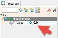
- For each value set the value in the properties window:
- Value [0]: 0
- Value [1]: 0.9
- Value [2]: 0.7
- Value [3]: 0.5
- Value [4]: 0.3
- Value [5]: 0.1
- Close the "Elements Window"
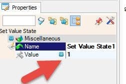
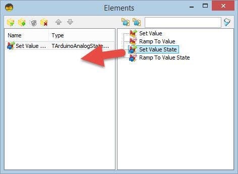
- Double click on the "AnalogValue1" and in the "Elements Window" drag "Set Value State" to the left and in the properties window set Value to 1
- Close the "Elements Window"
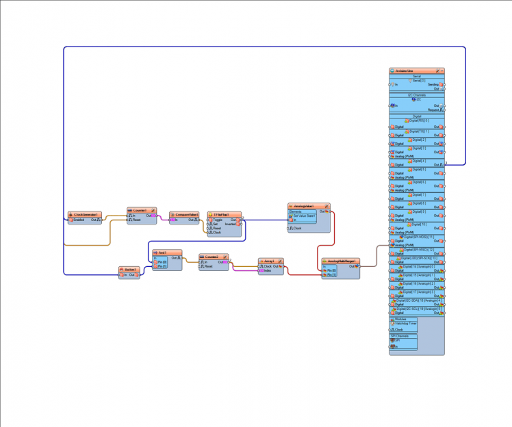
Step 6: In Visuino Connect Components
1 / 3
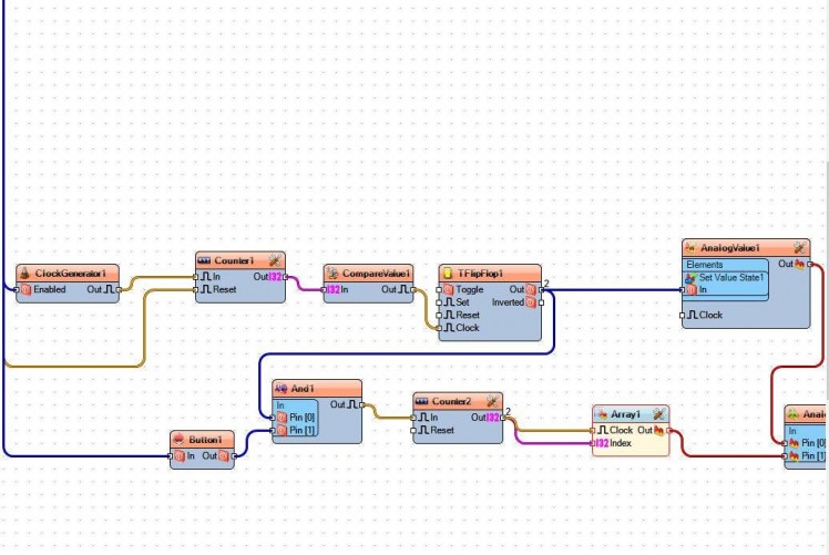
- Connect Arduino Digital pin [4] to Counter1 pin [Reset] and ClockGenerator1 pin [Enabled] and Button1 pin [In]
- Connect "ClockGenerator1" pin [Out] to "Counter1" pin [In]
- Connect "Counter1" pin [Out] to "CompareValue1" pin [In]
- Connect "CompareValue1" pin [Out] to "TFlipFlop1" pin [Clock]
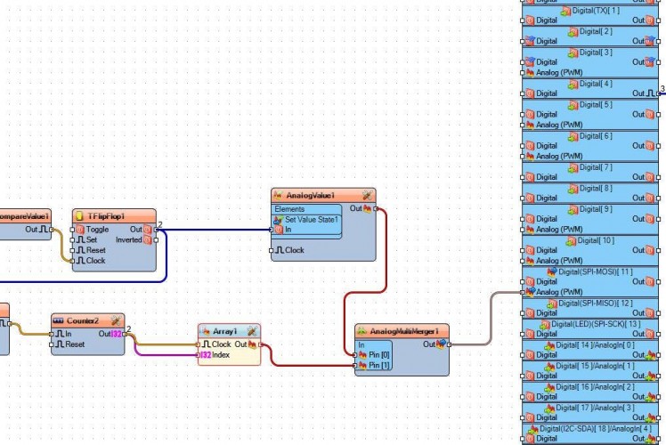
- Connect "TFlipFlop1" pin [Out] to "And1" pin[0] and "AnalogValue1 > Set Value State1" pin [In]
- Connect "AnalogValue1" pin [Out] to "AnalogMultiMerger1" pin [0]
- Connect "Button1" pin [Out] to "And1" pin[1]
- Connect "And1" pin[Out] to "Counter2" pin [In]
- Connect "Counter2" pin [Out] to "Array1" pin [Index] and pin[Clock]
- Connect "Array1" pin [Out] to "AnalogMultiMerger1" pin [1]
- Connect "AnalogMultiMerger1" pin [Out] to Arduino Analog(PWM) pin [11]
Step 7: Generate, Compile, and Upload the Arduino Code
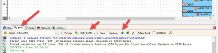
In Visuino, at the bottom click on the "Build" Tab, make sure the correct port is selected, then click on the "Compile/Build and Upload" button.
Step 8: Play
If you power the Arduino module, and Hold the button for 3s the LED will turn ON, If you now press the button for a short period the LED will change its brightness. if you again Hold the button for longer then 3s the LED will turn OFF.
Congratulations! You have completed your project with Visuino. Also attached is the Visuino project, that I created for this tutorial, you can download it and open it in Visuino: https://www.visuino.eu
Schematics, diagrams and documents
Code
Credits
Related products


Leave your feedback...