
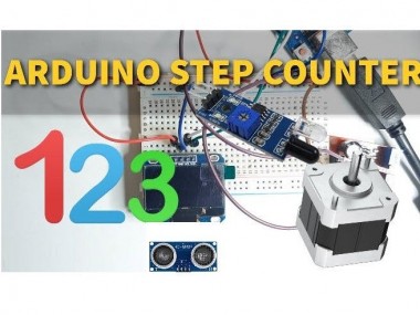
Simple Step Counter Using Arduino

Made by Ron / 3D Printing / Automotive / Robotics
About the project
In this tutorial we will learn how to make a simple step counter. This project is very useful in robotics.
Items used in this project
Hardware components

Story
In this tutorial we will learn how to make a simple step counter. This project is very useful in robotics or anywhere where you need to count something like how many steps the motor made or how many times the sensor detected something.
Watch the Video!
Step 1: What You Will Need
1 / 5
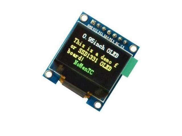
- OLED LCD Display
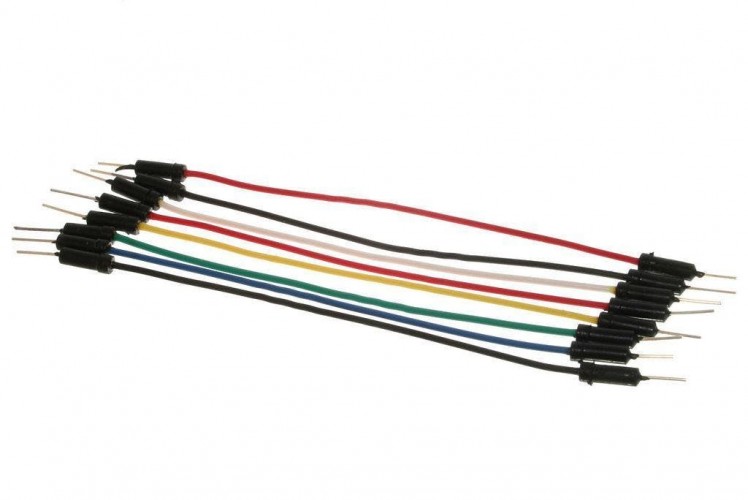
- Jumper wires
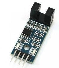
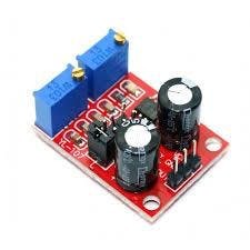
- Some sort of frequency generator, it can be another Arduino but in our case we will use a cheap 555 module.You can also connect a IR Encoder sensor
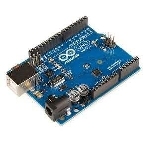
- Arduino Uno or any other Arduino board
- Visuino software: Download here
Step 2: The Circuit - Variation1 Using 555 Module As a Step Source
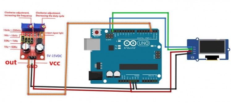
- Connect 555 module pin[VCC] to Arduino pin[5V]
- Connect 555 module pin[GND] to Arduino pin[GND]
- Connect 555 module pin[OUT] to Arduino Interrupt pin[2]
- Connect OLED Display pin[VCC] to Arduino pin[5V]
- Connect OLED Display pin[GND] to Arduino pin[GND]
- Connect OLED Display pin[SDA] to Arduino pin[SDA]
- Connect OLED Display pin[SCL] to Arduino pin[SCL]
Note if you are going to use some other source of frequency make sure that you connect (share) the GND with arduino GND.
Step 3: The Circuit - Variation2 Using Another Arduino As a Step Source
1 / 4
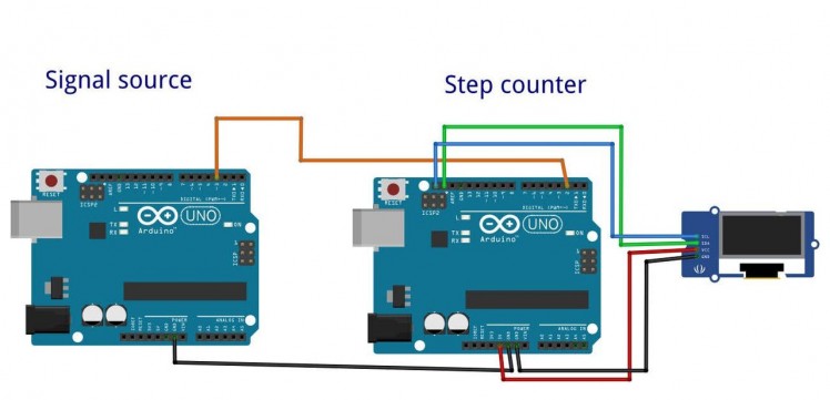
- Connect Arduino1 (Source) Digital pin[3] to Arduino2 Interrupt pin[2]
- Connect Arduino1 (Source) pin[GND] to Arduino2 pin[GND]
- Connect OLED Display pin[VCC] to Arduino2 pin[5V]
- Connect OLED Display pin[GND] to Arduino2 pin[GND]
- Connect OLED Display pin[SDA] to Arduino2 pin[SDA]
- Connect OLED Display pin[SCL] to Arduino2 pin[SCL]
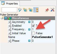
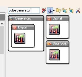
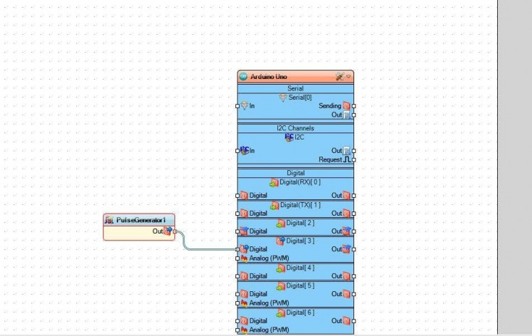
To program the source Arduino to put out signals just Open Another Visuino and place a "Pulse generator" component and connect its Out pin to Arduino digital pin 3, and in the properties you can set the frequency of the pulses.
Step 4: The Circuit - Variation3 Using IR Encoder Module As a Step Source
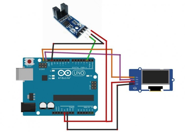
- Connect IR Encoder pin[VCC] to Arduino pin[5V]
- Connect IR Encoder pin[GND] to Arduino pin[GND]
- Connect IR Encoder pin[D0] to Arduino Interrupt pin[2]
- Connect OLED Display pin[VCC] to Arduino pin[5V]
- Connect OLED Display pin[GND] to Arduino pin[GND]
- Connect OLED Display pin[SDA] to Arduino pin[SDA]
- Connect OLED Display pin[SCL] to Arduino pin[SCL]
Step 5: Start Visuino, and Select the Arduino UNO Board Type
1 / 2
The Visuino: https://www.visuino.eu also needs to be installed. Download Free version or register for a Free Trial.
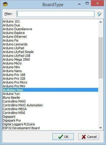
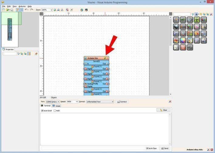
Start Visuino as shown in the first picture Click on the "Tools" button on the Arduino component (Picture 1) in Visuino When the dialog appears, select "Arduino UNO" as shown on Picture 2
Step 6: in Visuino Add,Set & Connect Components
1 / 6
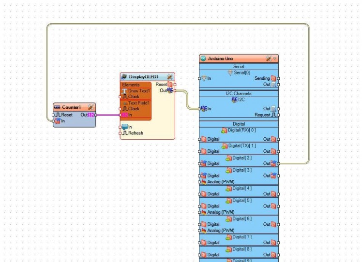

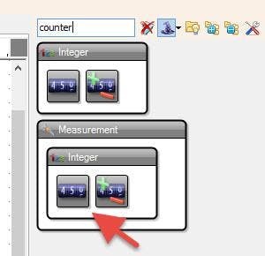
- Add "Counter" component
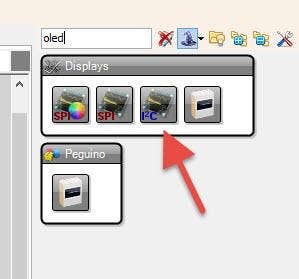
- Add "OLED" component
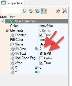
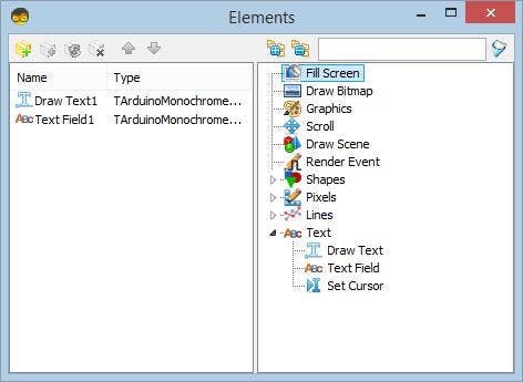
- Double click on the "DisplayOLED1" and in the Elements window
- drag "Draw Text" to the left side, and in the properties window set size to 2 and text to: Steps
- drag "Text Field" to the left side and in the properties window set size to 2 and Y to 40
- Close the Elements window
- Connect Arduino Digital Out Pin 2 to "Counter1" pin In
- Connect "Counter1" pin Out to "DisplayOLED1" > Text Field1 pin In
- Connect "DisplayOLED1" pin I2C Out to Arduino I2C In
Step 7: Generate, Compile, and Upload the Arduino Code
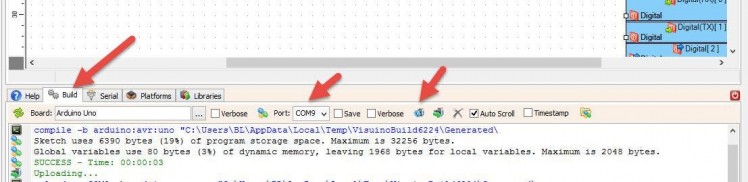
In Visuino, at the bottom click on the "Build" Tab, make sure the correct port is selected, then click on the "Compile/Build and Upload" button.
Step 8: Play
If you power the Arduino UNO module, the OLED Display will start to show the frequency in Hz that 555 module produces or Another arduino or IR Encoder.
Note: With 555 module you can adjust the frequency by rotating trimmers.
Congratulations! You have completed your project with Visuino. Also attached is the Visuino project, that I created for this tutorial, you can download it and open it in Visuino: https://www.visuino.eu
Attached Files: Step Counter and Steps Source project in case you will use another Arduino as a source of steps
Schematics, diagrams and documents
Code
Credits
Related products


Leave your feedback...