
Rgb Ledcube Using Neopixel Leds And Pcb

About the project
let's build an RGB LED CUBE using NEOPIXELS and PCB
Items used in this project
Hardware components

Software apps and online services
Story
Hello there
LEDs are one of the fascinating and attractive electronic components. We usually use LEDs for decoration. LED cubes are such a 3-dimensional decorative item. I have already built some led cubes like 2*2, 4*4 even build a 4*4 RGB LED cube using Charlie plexing method. These are interesting stuff but it took days to build a good looking LEDCUBE. Here once again I am going to make a 4*4 RGB LED cube but this time I am gonna use PCBs to build the cube which will magically reduce the time of making. Also, I am going to use WS2812B Neopixels, this gives more colours and easy programming. So let’s see how to make this.
Step 1: MATRIX LAYER CIRCUIT DIAGRAM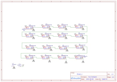
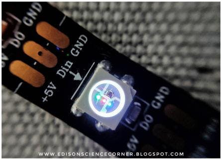
As always everything starts from a circuit. So first I decided on the type of LEDs. I am going with this WS 2812B Neopixels because these LEDs are capable of delivering RGB colours also we can control thousands of LEDs using a single input. This neopixel has 4 leads 5v, gnd, data in and data out. You can find more details from the datasheet The circuit is pretty simple we are making 4*4 matrixes. later we use 4 of these matrixes stack and make the 4*4*4 led cube. So this is the 4*4matrix we are just connecting the dout of first led to the second and so on.
Step 2: PCB DESIGNING AND FABRICATION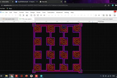
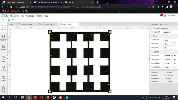
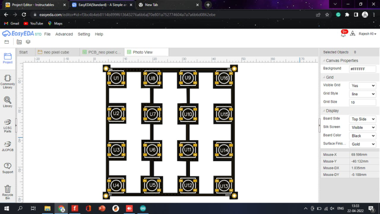
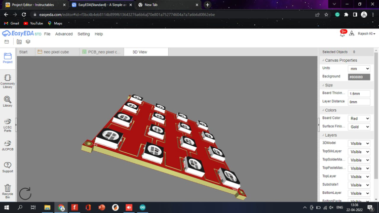
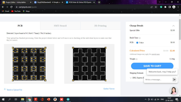

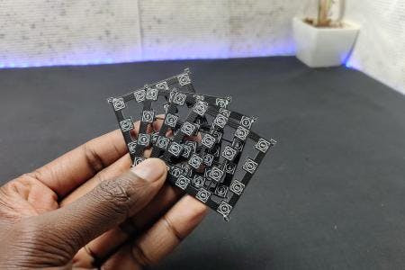
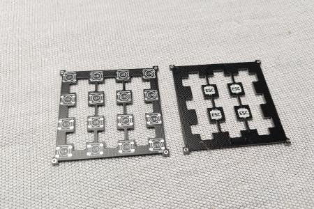
After designing the circuit I converted the design into a PCB and arranged the LEDs in a 4*4 matrix pattern and designed the PCB. I removed most of the PCB to get a better look. After finishing the design our PCB looks something like this. Now I generated the Gerber files and went to JLCPCB for PCB fabrication. JLCPCB gives 5 PCBs for just 2 dollars and PCB assembly starts from 0 dollars. I uploaded the Gerber and selected the colour and placed the order. After two weeks I received the PCBs and the look PCBs are nice and the quality is superb.
order your PCBs from JLCPCB only $2 for 5pcs 1-4 layer PCBs ;PCBA from $0
download the Gerber file from here
Step 3: COMPONENTS REQUIRED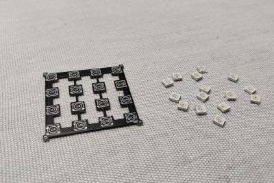
1. WS 2812B Neopixel led*64
2. Arduino pro mini
3.tp4056 charging module
4.3.7volt lithium-ion battery
5. on/off switch
6. button switch
7. copper wire
8.3d printed base
9. custom PCBs
Step 4: Making the Matrix Layer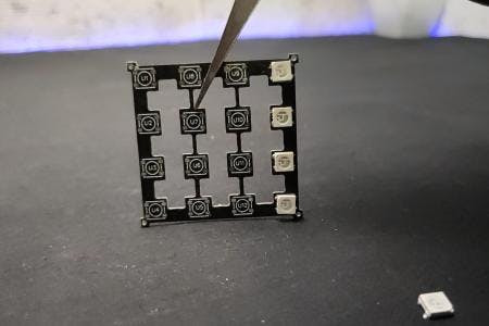
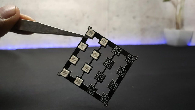
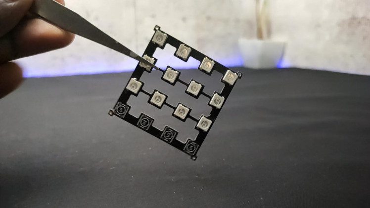
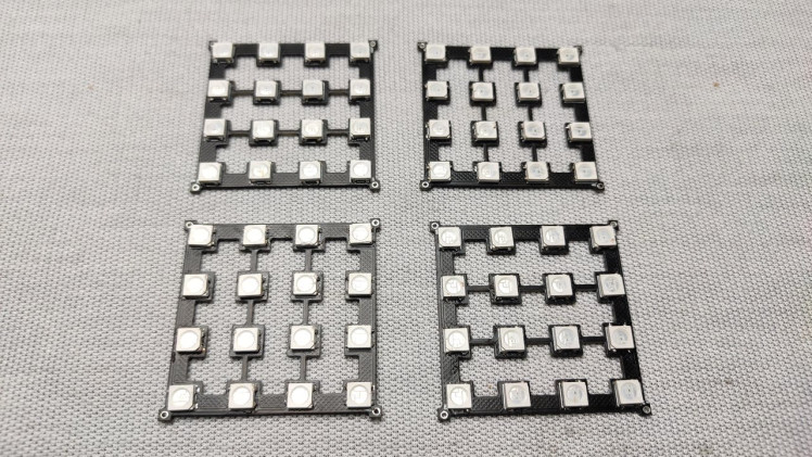
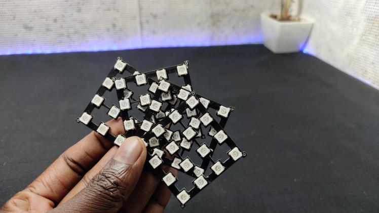
I grabbed the Neopixel LEDs and placed them on the PCB using a tweezer. After placing I solder the LED to the PCB using the normal soldering iron. You can use a hotplate for this process. After finishing the soldering of the first led I repeated the process for the remaining LEDs. After finishing the matrix I tested the matrix. And worked without any problem. Similarly, I made 3 more layers.Add TipAsk QuestionCommentDownload
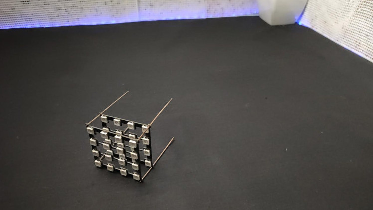
Step 5: Making the LED CUBE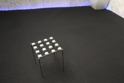
3 More Images
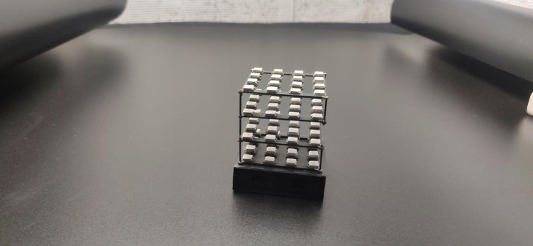
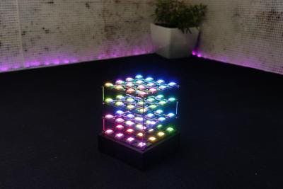
Now it’s time to stack matrixes one over the other for that I am using 1mm thick copper wire. We need four of them. First, I connected the 4 wires to the first layer and then inserted the other layers through the copper wire. and soldered the layer to the copper wire. I checked everything with the multimeter and tested once again after finishing all the layers our cube looks like this.
Step 6: Controller Circuit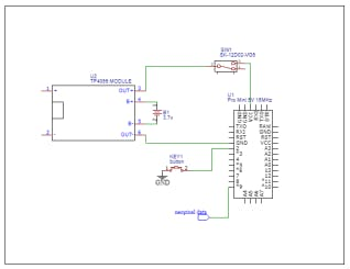
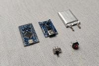
Now let’s build the controller circuit that we need an Arduino pro mini, a tp4056 with a li-ion battery, a button switch and an on/off switch.
Step 7: 3D Designing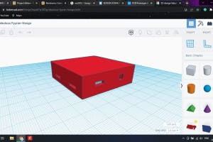
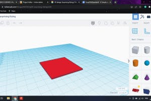
To enclose everything I designed a base box and its cover using tinkercad. also, I added slots for push button and on/off switch.
Step 8: 3D Printing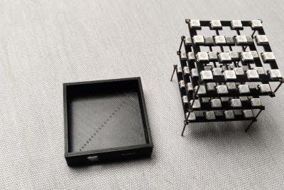
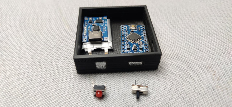
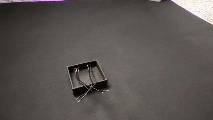
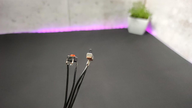
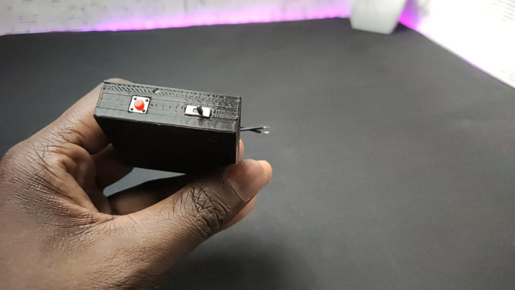
I 3d printed the design using my ender 3. here I used black PLA and 20% infill. After 3 d printing, first I connected flexible wires to the switch and button. Then I inserted the switches into its socket and secured them with hot glue. After that, I placed the tp4056 and the battery. now let’s place the cube on top of the base and finally, I placed the Arduino pro mini inside the enclosure.
Step 9: Controller Circuit Making


After placing everything inside the box I started soldering. I connected all grounds together, VCC of Arduino and Neopixel connected through the switch. finally, I placed the neopixel cube on top of the enclosure and connected the data in pin to D9.Add TipAsk QuestionCommentDownload
Step 10: Programming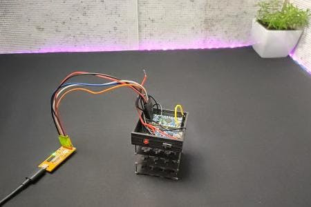
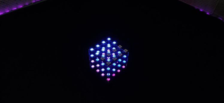
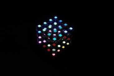
after finishing the soldering I uploaded the code to pro mini through a USB to TTL converter. So finally I printed the cap of the base and closed it. That’s the end of the long build. Rest is testing Now you can see the mesmerizing animations and colour patterns. You can make your own patterns with your ideas. Now enjoy the show.
Step 11: HAPPY MAKINGhttps://youtube.com/watch?v=7p8d5JzmReE%3Ffeature%3Doembed%26enablejsapi%3D1%26origin%3Dhttps%3A

So guys this is how I made an led cube using PCBs. you can download the circuit, code, and STL files Hope you enjoyed and learned something from my tutorial if so please like share and comment all up to you I will see you next time…..
Schematics, diagrams and documents
CAD, enclosures and custom parts
Code
Credits
Related products


Leave your feedback...