
Four-legged Robot Ensuring Intelligent Sprinkler Automation

Made by davmacario / 3D Printing / Artificial intelligence / Environmental Sensing / Plants / Robotics
About the project
FREISA, an acronym for "Four-legged Robot Ensuring Intelligent Sprinkler Automation, " continues the storyline of the B-AROL-O Team's saga
Project info
Difficulty: Moderate
Platforms: Raspberry Pi, ROS, OpenCV
Estimated time: 5 weeks
License: Creative Commons Attribution CC BY version 4.0 or later (CC BY 4+)
Items used in this project
Hardware components

Software apps and online services
View all
Story
Following their remarkable achievement in the OpenCV Spatial AI Contest with project ARNEIS last year, Gianluca and Gianpaolo have enthusiastically shared the enjoyment they experienced and the wealth of knowledge they gained from their participation in the contest. Their enthusiasm has now been passed on to Andrea, Davide, Eric, and Pietro, who have decided to register for the new OpenCV AI Competition 2023.
As we explained last year, we are B-AROL-O and we made #ARNEIS. What else can we make this year? #FREISA, of course!
In compliance with the Competition's rules, Gianluca and Gianpaolo will abstain from writing code this year (although for Gianpaolo, it hardly changes anything!) and act as Advisors. Nevertheless, they remain committed to generously offering their guidance and expertise, aiming to educate the aspiring Padawans by sharing the invaluable insights they acquired from the Jedi Knights (yes, Satya, Phil, Joseph and Brandon – we're talking about you!).
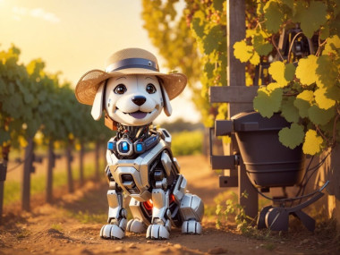
What is FREISA all about?The objective of this project is to create a prototype of a dog robot that utilizes computer vision to water plants.
As the old saying goes, "A picture is worth a thousand words...":
FREISA main use case
- In an arena with dried plants and watered plants
- A quadruped robot
- Identifies dried-up plants
- Sprinkles water on dried plants
The Arena
Initially, we contemplated using vineyards as our setting, aligning with our name, FREISA. However, this choice presented certain challenges.
Primarily, the vine leaves grow at a height of at least 40 cm from the ground, significantly higher than the intended height for the dog robot we planned to employ.
Secondly, the terrain where vines are typically cultivated, notably in Italy, tends to be uneven, posing navigation difficulties for a robot.
Taking everything into account, we chose a more "controlled" environment—a household garden with tomato plants. Nonetheless, this decision doesn't rule out the possibility of continuing our project and potentially introducing our MiniPupper to the vineyards in the future!
Quadruped Platform
Prior to selecting the MiniPupper 2 created by MangDang—an open-source initiative derived from the Stanford Pupper's code developed by the Stanford Robotics club and centered on a Raspberry Pi 4—we explored various other options for our robotic system.
Some other possibilities were:
- Bittle and Nybble from Petoi
- UGOT Robotic Kit - a successful Kickstarter project (https://www.kickstarter.com/projects/ubtech/ugot-robotic-kit-future-crafted-now)
- Unitree Go1 Robotic Dog (https://it.aliexpress.com/item/1005006075207418.html)
The choice of the robot was also motivated by the familiarity with the MiniPupper project from one member of our team and by the interest of the open-source community in this project.
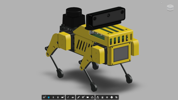
Camera Systems
The camera we used in our implementation is the OAK-D-Lite by Luxonis, which allows us to run Computer Vision pipelines on dedicated hardware without consuming resources of the Raspberry Pi that controls the motion of the robot. This required taking into account the additional weight overhead to be supported by the MiniPupper 2 and 3D print custom brackets for support. Following this approach, the robot can potentially be independent of any external infrastructure, such as a dedicated computer on which to perform "heavier" tasks.
The only other alternative we considered was the Raspicam V2, but this would have required us to run the inference on the Raspberry Pi CPU, causing computational overhead and a slower system overall.
Water and Targeting Systems
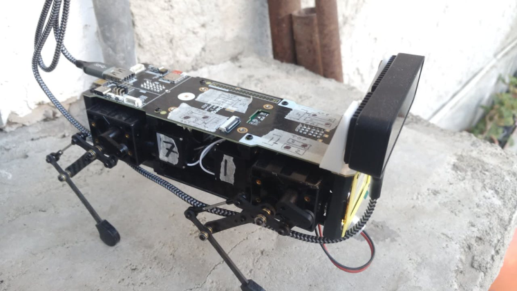
One of the aspects that was discussed more was the position of the sprinkler and its mechanism. We ended up placing the sprinkler in a pelvic position, with the water reservoir right above, as all other alternatives were problematic in terms of either weight distribution or physical design.
Navigation System
We decided to develop an FSM to control the robot's movement. This approach is well suited to work alongside the camera providing the inference results, and allows us to define the changes in the state when the camera observes specific targets.
The alternative could be to integrate the ROS2 SLAM toolbox for robot navigation, which would require additional work in the integration of the different parts of the application.
FREISA System ArchitectureFREISA comes together as different software and hardware components that communicate. This section discusses all these components after giving a detailed description of the overall architecture.
This architecture has been documented using SysML diagram prepared with Eclipse Capella.
This diagram shows the main actors of the system:
FREISA - Operational Entities

FREISA - Operational Entities
- The navigation system (OS)
- Mini Pupper 2
- The vision system (OAK-D-Lite)
- The sprinkler
Interconnections between the operational entities
Interconnections between the operational entities

Interconnections between the operational entities
In this diagram, the different interconnections between the operational entities are shown: the Mini Pupper must have a navigation system running on the local Raspberry Pi 4 to move around the Arena and recognize the targets, a vision system (camera connected through USB) to see the different targets, and a mechanical sprinkler controlled via the Raspberry Pi's GPIO, to water the targets that need it.
Activities of the system
Activities of the system

Activities of the system
The activities that the system needs to perform are the following:
- Recognition of the targets (via Computer Vision)
- Check data
- Configuration
- Recognition of the position of the target (interpreting the CV results)
- External communication
- Spray water (decide to activate sprinkler)
- Control of the sprinkler (actuation)
- Motion control of the puppy
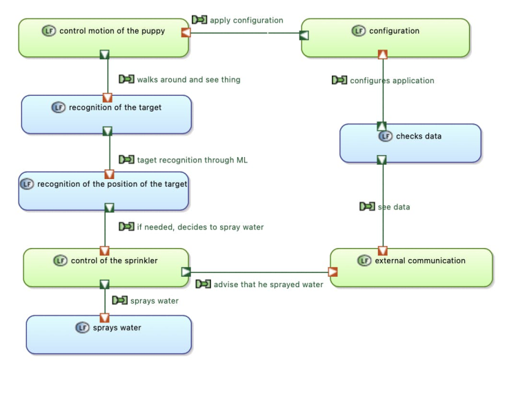
Logical Architecture
The figure below represents the first instance of the physical architecture, i.e., our setup, showing that we used different "puppies" in the world: Turin (Italy), Chicago (USA), and Nantes (France). As explained above, we used a Raspberry Pi, Docker, and different OAK-D-Lite cameras for the project. The following is the general logical architecture of the system, with the functions it has to perform:

- Check data: the external user can see the results from the HTTP server and other parts of the code to check if the system is working.
- Configuration: the code can be configured by the external user to adapt it to different kind of plants.
- Motion control of the puppy: Motion control is very important to ensure good work from the puppet.
- Recognition of the target: Through the vision and navigation systems, the Puppy must walk around the arena and recognize the plants he needs to take care of.
- Recognition of the target's position: Once a target is spotted, it must recognize the position of the target so it can water it more efficiently.
- Control of the Sprinkler: If the plant is recognized as "in need", the Puppy will move the sprinkler to spray the water.
- Sprays water: Through the sprinkle, it waters down the target if he notices he needs to.
- External communication: Through Bluetooth or Wi-Fi or any other wireless communication protocol available on the Raspberry Pi, the Puppy can advise its owner that a plant has been watered down.
Physical Architecture
The following diagram details the main physical components of the FREISA project.
Physical Components

Physical Components
MiniPupper 2The FREISA team believes that Quadruped Legged Platforms are ideally suited for a range of unstructured outdoor applications due to the ability to navigate complex terrain. Below a table listing the strengths and weaknesses of mobile platforms.
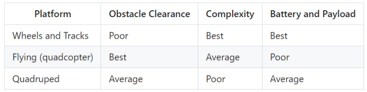
The minimum number of motors (intended as degrees of freedom – DoFs) for a quadruped platform is 8 DoF to achieve quadruped motion. At least 12 DoF are needed to achieve full quadruped motion, allowing implementation of a roll axis on the body, and all manners of sideways motion.
Simple quadruped robots have a simple open-loop controller that sets the angles of the motors. This kind of controllers always has legs moving and has a poor obstacle clearance and motion precision.
A dynamic closed-loop controller is incredibly complex, as it is required to unleash the obstacle clearance ability of a legged platform, be able to feel slipping, falling and disturbances on different surfaces, and compensate accordingly.
For this project, we stuck with the open-loop controller, but we are exploring ways to integrate a proper closed-loop controller inside the MiniPupper.
This complexity deters the use of quadruped robots compared to other platforms, Many military, industrial, and open-source quadruped designs are currently being explored in robotics.
For the scope of this project, we had a series of requirements:
- Affordability (< 500$)
- Open-Source
- 12 DoF
- High quality servo motors with feedback
- Raspberry Pi
- ROS2
- At least ten minutes of battery life
- Enough payload clearance to mount attachments
One of our team members had experience with the first release of the MiniPupper platform that made use of regular PPM open-loop motors, The second release upgrades motor to digital with position feedback.
The choice of platform
MiniPupper 2 comes with a Ubuntu (22.04) image with a UDP-based orchestrator, the image used to build the application for the scope of this competition. MiniPupper 2 also has a ROS2 image that the Authors are planning to use for future applications.
There are cheaper quadruped platforms in the market, but to our knowledge, they achieve their price point by cutting on DoFs, servo quality, feedback, or removing the onboard SBC.
Material of MiniPupper 2 assembly kit

Material of MiniPupper 2 assembly kit
Follow assembly instructions https://www.youtube.com/watch?v=-TDyncSvzI8
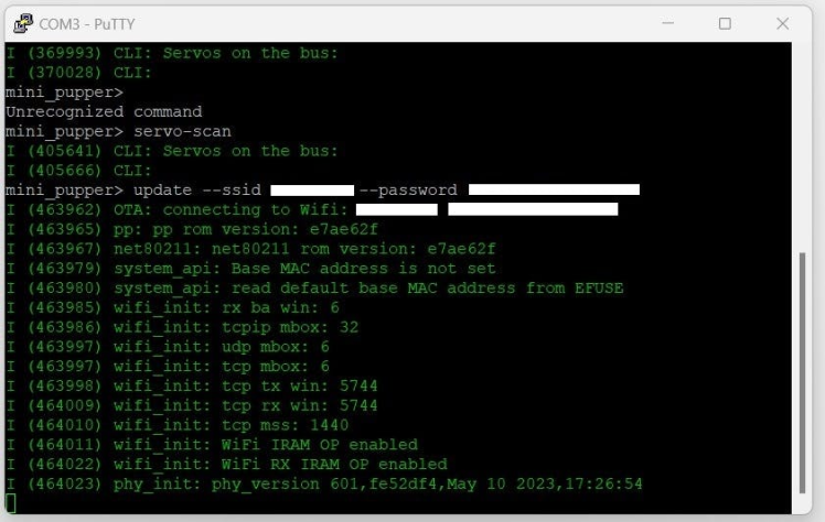
Carefully map the motors with the correct ID and make sure they are in the neutral position. 500Kb UART link, SCS (Smart Control Servo) protocol from FeeTech.

Connect to ESP32 via USB-C port via SSH serial 115200 baud. Make OTA update of the ESP32 firmware via WiFi. The ESP now lists all twelve servo.
Finish assembly of MiniPupper

Calibration and Testing
Execute the calibration tool with the goal of having the motors near their neutral position and Mini Pupper parallel to the terrain. Remember to keep the arrows key pressed to move the motors as it is a small precise movement. If the motors are too close to extremes, remove the leg, put the motor in neutral position and reinstall the leg.
Execute test programs in /demos:
displayhaptic_demo: pulling the front right leg should have the other legs do the opposite motion. It tells you the calibrations went fine and the motor IDs are OK
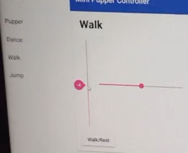
Install the web controller by following the instructions.
Go to http://IP_ADDRESS:8080 and you should see the MiniPupper web controller that controls the robot via UDP commands.
Activate the controller AND the motors. Set the height of the robot in the Dance page. Now the sliders in the walk page should work. Check the walking gait of MiniPupper.
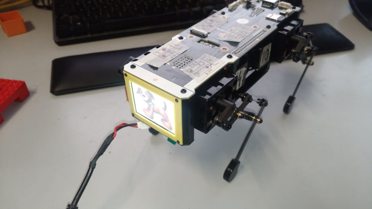
In a nutshell, two things distinguish a FREISA dog from a MiniPupper: the first is strong eyesight, and we cannot tell the name of the other :-)
Here, we explain the modifications to the "standard" MiniPupper 2 robot we had to perform to achieve our use case.
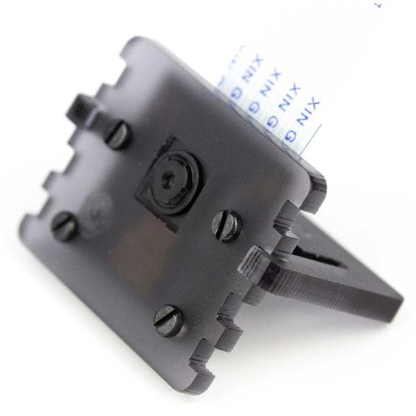
Installing the OAK-D-Lite
To add the OAK-D-Lite camera, we 3D printed a custom support bracket.
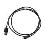
It is necessary to use a high bandwidth, right-angle USB-A to USB-C cable of the appropriate length to connect the camera to the Raspberry Pi 4.
The camera requires a large amount of bandwidth, so lower-quality cables might not work.
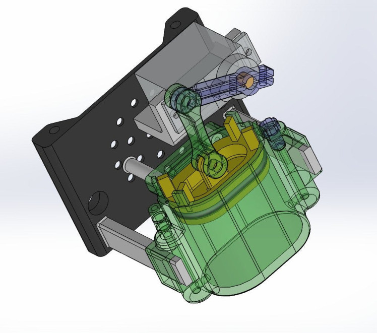
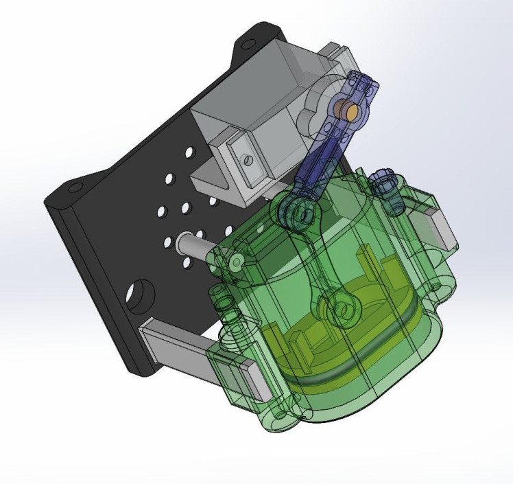
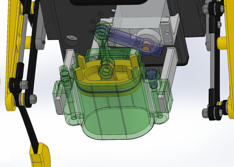
Design of the freisa-sprinkler
The FREISA team is grateful to Gianfranco Poncini who is the mind behind the mechanical design of freisa-sprinkler.
1 / 3
The STL files of all the required parts—as well as some instructions on how the parts should be put together—are available under https://github.com/B-AROL-O/FREISA.
Addingthesprinkler axis
Our application requires an additional axis to be able to control the sprinkler. There are many options to add more axes:
- Use PPM channels on ESP32: requires firmware upgrade of ESP32 and additional commands
- Add a PPM channel to the GPIO: possible route, there are limited free IOs on the GPIO limiting quality of the PPM control
- Add a 13th channel to the servo bus: Not possible, the bandwidth of the channel is needed for position, position feedback and torque feedback of the servo
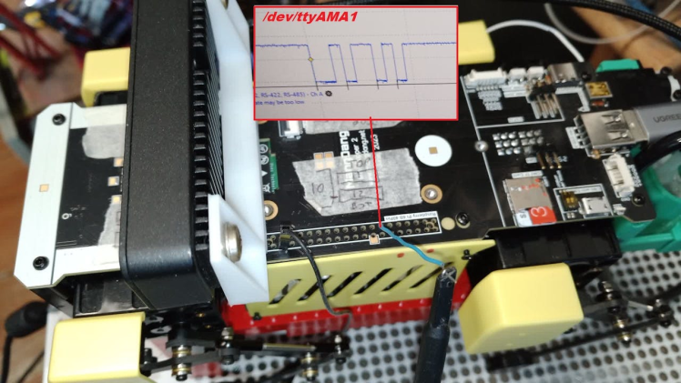
- Add a new SCS servo bus for the 13th channel to the GPIO: best solution, Pupper has the
/dev/ttyAMA1serial port free that maps to the GPIO and has easy access
We created an additional servo bus on the RPi GPIO as the most forward-looking option. It easily allows adding multiple additional axes to the platform with no extra work.
A test program in /demos allows to test the 13th axis by implementing just the set position command for ease of use.
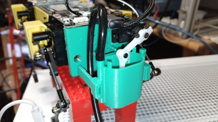
3D Print and SprinklerAssembly
We went through a few iterations of the design, which required improving the supports of the servo motor and the tightness of the piston O-RIng.
After 3D printing, nuts and ball bearings were embedded in the plastic using a soldering iron, followed by the replacement of the original back plate.
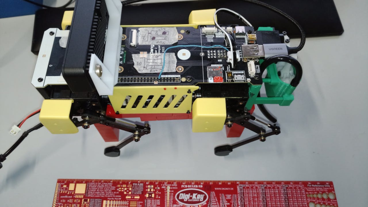
Ready for Software Development
The MiniPupper 2 base assembly, base software, and custom hardware extensions are complete and tested. What follows is the development of the software components for the Vision and the Demo.
This section presents a description of the "vision" part of the application, which provides the robot with information about the environment around him.
This application component controls the OAK-D-Lite camera, on which it is possible to deploy pre-trained computer vision models (based on deep neural networks) to locate the target plants and analyze the leaves' conditions.
Computer vision models
At the foundation of this component are the two neural networks allowing the plants to be located (performing trunk segmentation) and the leaves to be detected and classified as either healthy or unhealthy. Both models are based on the YOLOv8 architecture and have been trained on a custom data set, which we uploaded to Roboflow.
tomato-trunk-segmentation

tomato-trunk-segmentation
tomato-leaves-healthy-unhealthy-detection
tomato-leaves-healthy-unhealthy-detection

tomato-leaves-healthy-unhealthy-detection
Training the models
Model training is possible on Roboflow's servers. However, we chose to train our neural networks locally because the free Roboflow plan only provides a limited amount of "credits" to be spent on training and experimenting with the frameworks for deep learning on our own computers.
Our set-up consisted of one desktop computer running Ubuntu 23.04 (AMD Ryzen 2600X CPU, 48 GB of RAM, and NVidia GTX 1660 super GPU), remotely accessed through a container with JupyterLab using the graphics card.
Thanks to the Roboflow APIs, exporting the data sets is easy and allows for effortless training on remote hardware.
The two neural networks have been trained for 200 epochs each, and the final models have been saved for later use on the OAK-D-Lite camera.
The OAK-D-Lite module
Once the neural networks have been trained, deploying them on the OAK-D-Lite camera is necessary.
This section describes the software that performs these operations. The source code is publicly available on GitHub at https://github.com/B-AROL-O/FREISA/tree/main/code
VisionController
The first piece of software is the VisionController, a Python class defined to control the camera by providing methods to load models, launch pipelines, and collect the results. These operations are performed using the DepthAI library from Luxonis, which allows to define pipelines through which to process information coming from the video cameras in the OAK-D-Lite using custom neural networks and, most importantly, to retrieve this information over the USB connection in a straightforward way.
To be used by the OAK-D-Lite camera, the models need to be converted from YOLOv8 to .blob, plus a JSON file containing setup information necessary to instantiate the vision pipelines. This step was carried out using the conversion tool provided by Luxonis.
VisionWebServer
To provide access to the VisionController methods, we implemented an HTTP server that provided standard (REST) APIs to control the camera over port 9090. This way, other application components can act on the camera by simply performing HTTP requests.
DockerContainer
Another essential advantage of the definition of a REST API is that the OAK-D-Lite module can be run independently from the other components as a Docker container.
Indeed, we also provided the Dockerfile defining the image (based on the python:3.10-bullseye image), which can be used to run the whole module as a container, provided it has access to the USB bus to be able to communicate with the camera.
We created a functioning demo, which can be seen in action on YouTube.
FREISA demo video for OpenCV AI Competition 2023Our robot is able to successfully locate a target plant, approach it, and analyze the leaves before adjusting its position and sprinkling water on the plant. This prototype has been tested on stable terrain, as reported in the video.
Possible follow-ups
Due to our limited available time, we had to make compromises in our selections. However, the project's open-source nature allows for numerous enhancements from external contributors.
The primary challenge to address initially involves choosing an alternative setting, referred to as the "arena, " for placing the robot.
The design of the computer vision module enables the camera to function on various targets by utilizing correctly formatted models. This capability expands the robot's versatility in handling diverse types of plants.
The difficulty in selecting a different arena primarily pertains to the potential terrain conditions. This issue can be addressed by implementing a more complex framework for controlling the robot's motion, such as ROS Nav2 (SLAM), or by employing Mesh Navigation in conjunction with Move Base Flex, as demonstrated at https://bit.ly/ROSCon233DMesh. These frameworks can also offer additional benefits, such as environment mapping.
Another avenue for enhancing the application's performance involves utilizing the stereo cameras of the OAK-D-Lite to estimate the target's distance. This data could be leveraged to provide more precise instructions to the motion control system, enabling faster and more accurate operations.
How to stay in touchYou may follow @baroloteam on Instagram or @baroloteam on Twitter (now X) to get notified about the progress of the FREISA project.
Please report bugs and feature requests on https://github.com/B-AROL-O/FREISA/issues, or DM B-AROL-O Team on X about security issues or other non-public topics.
Appendix 1: Acronyms- AI: Artificial Intelligence
- ARNEIS: Automated Recognizer, Network-Enabled, Items Sorter. See https://arneis.readthedocs.io
- B-AROL-O: See https://github.com/B-AROL-O
- BLE: Bluetooth Low Energy. See https://en.wikipedia.org/wiki/Bluetooth_Low_Energy
- BT: Bluetooth®. See https://www.bluetooth.com
- CLI: Command-Line Interface
- CPU: Central Processing Unit
- CV: Computer Vision
- DNN: Deep Neural Network
- DNS: Domain Name System. See https://en.wikipedia.org/wiki/Domain_Name_System
- DoF: Degree(s) of Freedom
- ESP32: A family of System-on-a-chip microcontrollers. See https://en.wikipedia.org/wiki/ESP32
- FPU: Floating Point Unit
- FSM: Finite State Machine
- GPIO: General Purpose Input/Output
- HTTP: Hypertext Transfer Protocol. See https://en.wikipedia.org/wiki/Hypertext_Transfer_Protocol
- HW: Hardware
- JS: JavaScript. See https://www.javascript.com
- JSON: JavaScript Object Notation. See https://www.json.org
- JWT: JSON Web Tokens. See https://jwt.io
- K3S: Lightweight Kubernetes. See https://k3s.io
- K8S: Kubernetes. See https://kubernetes.io
- K9S: See https://k9scli.io
- LED: Light Emitting Diode
- MQTT: See https://mqtt.org
- NN: Neural Network
- OAK: OpenCV AI Kit
- OpenCV: See https://opencv.org
- PDF: Portable Document Format. See https://en.wikipedia.org/wiki/PDF
- PPM: Pulse Position Modulation. See https://wikipedia.org/wiki/Pulse-position_modulation
- PWM: Pulse Width Modulation. See https://wikipedia.org/wiki/Pulse-width_modulation
- REST: REpresentional State Transfer. See https://wikipedia.org/wiki/REST
- ROS: Robot Operating System. See https://www.ros.org
- SCS: Smart Servo Control
- SLAM: Simultaneous Localisation and Mapping
- SSH: Secure Shell Protocol. See https://en.wikipedia.org/wiki/Secure_Shell
- STL: See https://en.wikipedia.org/wiki/STL_(file_format)
- SW: Software
- SysML: A profile of UML v2. See https://sysml.org
- UART: Universal Asynchronous Receiver-Transmitter. See https://wikipedia.org/wiki/Universal_asynchronous_receiver-transmitter
- UI: User Interface
- UML: Unified Modeling Language. See http://uml.org
- USB: Universal Serial Bus. See https://en.wikipedia.org/wiki/USB
Computer Vision
- Tomato leaves model: tomato-leaves-healthy-unhealthy-detection
- Tomato trunk segmentation: tomato-trunk-segmentation
Roboflow datasets
Roboflow and training models
- Setup guide for Linux workstation
- NVIDIA Container Toolkit install guide
- Getting started with Roboflow
- JupyterLab + Docker setup guide
- Adding GPU support to Docker
- DepthAI website
- Roboflow's "getting started" guide
- Roboflow tutorials
Mini Pupper
- https://www.mangdang.net/
- Mini Pupper User Manual
- Main GitHub repository: https://github.com/mangdangroboticsclub/mini_pupper
- Mini Pupper 2: Open-Source, ROS2 Robot Kit for Dreamers on Kickstarter
- Mini Pupper 2: Open-Source, ROS2 Robot Kit on Indiegogo
CAD, enclosures and custom parts
Code
Credits
Related products


Leave your feedback...