
Exhibit: The Primal Display

Made by electrouser829 / Displays / Environmental Sensing / Sensors / Weather / IoT
About the project
This very simple protip connects an LCD to a Raspberry Pi to display any data you need, like readings from a temperature sensor.
Project info
Difficulty: Easy
Platforms: Adafruit, Microsoft, Raspberry Pi
Estimated time: 2 hours
License: MIT license (MIT)
Items used in this project
Hardware components


Story
Introduction
LCD is a very useful add-on to any project. This very simple protip connects LCD to Raspberry Pi to display any data you need. In our case, we will display readings from a temperature sensor.
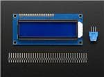
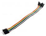
Hardware
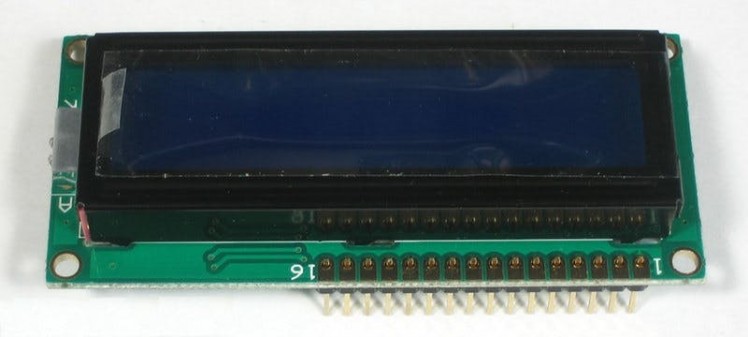
We need an inexpensive HDD44780 compatible LCD, Raspberry Pi 3 and temperature and humidity sensor DHT11, micro SD card and power source, 1-2 potentiometers, breadboard and some wires. LCD, breadboard, wires, potentiometers and sensor can be found in this kit. We are going to connect LCD using 6 GPIO pins. While there is a way to connect using I2C, this is the most direct method and has important benefits:
- Allows for inexpensive LCDs to be used
- Does not require any I2C drivers
- Will not steal the only serial port on the Pi.
 6 GPIO Pins Option
 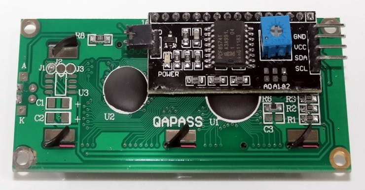 I2C Option
Wiring Things Up
We will have couple options connecting LCD screen: simple 4 bit connection with one potentiometer to handle contrast and brightness and a bit more complex 8 bit connection with advanced control over contrast and brightness with 2 potentiometers. The potentiometers can also be replaced with 1K or 3K Ohm resistors.
Each character and command is sent to the LCD as a byte (8 bits) of data. So in 4 bit mode, the byte is split into two sets of 4 bits which are sent one after the other over 4 data wires. In theory 8 bit mode transfers data twice as fast as 4 bit mode, since the entire byte is sent all at once over 8 data wires. However, the LCD driver takes a relatively long time to process the data, so no matter which mode is being used, you will not notice a real difference in data transfer speed between 8 bit and 4 bit modes.
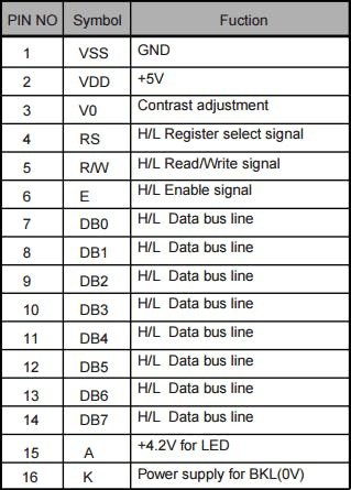 LCD Pin Layout
The data pins (DB0-7 pins 7-14) are straightforward. They are sending data to the display (toggled high/low). We will only be using write mode and not reading any data.
The register selectpin (RS pin 4) has two uses. When pulled low it can send commands to the LCD (like position to move to, or clear the screen). This is referred to as writing to the instruction or command register or to send data to the screen.
The read/writepin (R/W pin 5) will be pulled low (write only) as we only write to the LCD in this protip.
The enablepin (E pin 6) will be toggled to write data to the registers.
Simple LCD Connection
- Pin #1 of the LCD goes to ground (black wire)
- Pin #2 of the LCD goes to +5V (red wire)
- Pin #3 (Vo) connects to the middle of the potentiometer (orange wire)
- Pin #4 (RS) connects to the Cobbler #37 (yellow wire)
- Pin #5 (RW) goes to ground (black wire)
- Pin #6 (EN) connects to Cobbler #35 (orange wire)
- Skip LCD Pins #7, #8, #9 and #10
- Pin #11 (D4) connects to cobbler #33 (white wire)
- Pin #12 (D5) connects to Cobbler #31 (gray wire)
- Pin #13 (D6) connects to Cobber #29 (violet wire)
- Pin #14 (D7) connects to Cobber #23 (blue wire)
- Pin #15 (LED +) goes to +5V (red wire)
- Pin #16 (LED -) goes to ground (black wire)
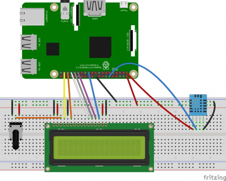 Simple LCD Connection Circuit Diagram
Advanced LCD Connection
- Pin #1 of the LCD goes to ground (black wire)
- Pin #2 of the LCD goes to +5V (red wire)
- Pin #3 (Vo) connects to the middle of the potentiometer (orange wire)
- Pin #4 (RS) connects to the Cobbler #37 (yellow wire)
- Pin #5 (RW) goes to ground (black wire)
- Pin #6 (EN) connects to Cobbler #35 (orange wire)
- Pin #7 (D0) connects to cobbler #40 (blue wire)
- Pin #8 (D1) connects to cobbler #38 (blue wire)
- Pin #9 (D2) connects to cobbler #36 (blue wire)
- Pin #10 (D3) connects to cobbler #32 (blue wire)
- Pin #11 (D4) connects to cobbler #33 (white wire)
- Pin #12 (D5) connects to Cobbler #31 (gray wire)
- Pin #13 (D6) connects to Cobber #29 (violet wire)
- Pin #14 (D7) connects to Cobber #23 (blue wire)
- Pin #15 (LED +) goes to +5V (red wire)
- Pin #16 (LED -) goes to ground (black wire)
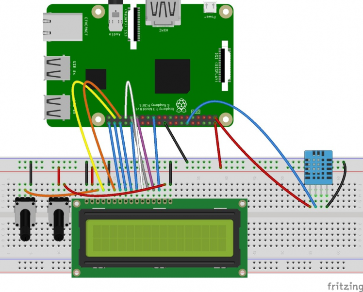 Advanced LCD Connection Circuit Diagram
INTERESTING:
Now we have 2 potentiometers: left one is responsible for contrast and right one is responsible for brightness. You may noticed we removed 5V wire (red one) from contrast potentiometer as there is no need in additional voltage handling because we have second potentiometer responsible for brightness.
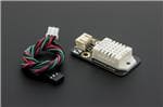
DHT11 Sensor Connection
DHT11 sensors can have 3 or 4 pins options however it does not matter as it uses only 3 pins to read the data in any case, if you have 4 pins sensor you need to connect only Vcc, Signal/Data and Ground pins and ignore the 4th one. On schematics above you can see 4 pins sensor connection.
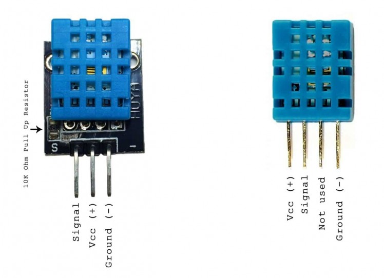 DHT11 Sensor: 3 and 4 Pins Options
IMPORTANT:
DHT11 sensor requires from 3.3V to 5V. First, let's connect DHT11 sensor to 3.3V Raspberry Pi pin 1 if it works this voltage is enough if readings are weird or there are no readings at all try connecting it to 5V Raspberry Pi pin 2. This protip uses 3.3V.
So far so well, after we connected Vcc and Ground pins we need to wire sensor's signal connector to Raspberry Pi physical pin 12 (GPIO 18).
Required Libraries
Before we proceed to the exact coding we need to double check if we have required libraries for display and sensor and install them if they are missing.
Just to double check (a bit of paranoia :)) we have all necessary Python stuff:
sudo apt-get install build-essential python-dev
RPLCD Python Library
The RPLCD library can be installed from the Python Package Index, or PIP. It might already be installed on your Raspbian, but if not, run this command to install it:
sudo apt-get install python-pip
After you get PIP installed, install the RPLCD library by entering:
sudo pip install RPLCD
Adafruit DHT11 Python Library
We are using the Adafruit DHT11 Python library. You can download the library using Git, so if you don’t have Git installed on your Raspberry Pi run this command:
sudo apt-get install git
Alternately you can try:
sudo apt-get install git-core
IMPORTANT:
If you get an error with alternative Git installation, run:
sudo apt-get update
sudo apt-get install git-core
Now, run command to download the library from Git:
git clone https://github.com/adafruit/Adafruit_Python_DHT.git
Go to new directory with:
cd Adafruit_Python_DHT
And install the library with:
sudo python setup.py install
Let's move to scripting.
Python Script
We are going to use Python to program our display and sensor. I use Visual Studio as IDE but you can use anything else you prefer to work with.
First, we need to connect to the Pi via SSH (with PuTTY for example). Then, we'll use a script called temperature.py.
To create the script, we can use the nano editor. After connecting to your Pi, run the following command to create a file called temperature.py:
sudo nano temperature.py
Then, paste the following code (8-bit option) into that file, and press CTRL-X to exit, and Y to save when prompted.
#!/usr/bin/python
import RPi.GPIO as GPIO
import time
import Adafruit_DHT
from RPLCD import CharLCD
# We call a RPi.GPIO built-in function GPIO.cleanup() to clean up all the ports we've used
GPIO.cleanup()
# Now setup LCD display pins (8-bit mode)
lcd = CharLCD(numbering_mode=GPIO.BOARD, cols=16, rows=2, pin_rs=37, pin_e=35, pins_data=[40, 38, 36, 32, 33, 31, 29, 23])
# Get senosr readings and render them in a loop
while True:
   # Get sensor's readings
   # IMPORTANT: 11 is sensor type (DHT11) and 18 is GPIO number (or physical pin 12)
   humidity, temperature = Adafruit_DHT.read_retry(11, 18)
   print('Temp: {0:0.1f} C  Humidity: {1:0.1f} %'.format(temperature, humidity))
   # Clear and set initial cursor position for LCD display
   lcd.clear()
   lcd.cursor_pos = (0, 0)
   # Render temperature readings
   lcd.write_string("Temp: %d C" % temperature)
   #  Move cursor to second row
   lcd.cursor_pos = (1, 0)
   # Render humidity readings
   lcd.write_string("Humidity: %d %%" % humidity)
   # Pause execution for 5 seconds
   time.sleep(5)
The example above uses 8-bit connection option with Raspberry Pi’s physical pin numbers for LCD display, not the BCM or GPIO numbers. I’m assuming you have your LCD connected the way it is in the diagrams above, but you can always change pins in case you need. Simple 4-bit connection code is attached in Code section.
IMPORTANT:
Please read comments in code, to get better understanding of what is going on.
Alternately you can download ready to use code from Git repository provided in Code section.
Conclusion
Hardware done, coding done, now we need to auto-run our display and sensor script on Raspberry Pi boot. I will describe the best one (at least from my point of view). You can check other options to run this automatically on boot here.
Runlevel (rc.local) Setup
I would recommend this approach because it is really straightforward, also it helps to run your script pretty soon after Raspberry Pi boots. Update rc.local file by running:
sudo nano /etc/rc.local
and adding line of code before the final exit 0:
/usr/bin/python /home/pi/temperature.py &
Please notice several important points:
- If your command runs continuously (perhaps runs an infinite loop) or is likely not to exit, you must be sure to fork the process by adding an ampersand to the end of the command. Otherwise, the script will not end and the Pi will not boot. The ampersand allows the command to run in a separate process and continue booting with the process running.
- Be sure to reference absolute filenames rather than relative to your home folder.
-
You apparently don't need the
sudohere, since rc.local runs as root.
That's it, we all set, restart your Raspberry Pi and check how it works. You could notice a green shining button which plays role of power on and off switch. If you are interested in how to implement it you can check this article.
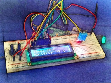
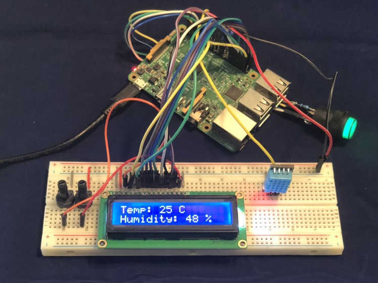 Completed Project
I hope reading this article was worth it and gave you some insight how you can enrich your project with installing LCD to display any data you need!
Schematics, diagrams and documents
Code
Credits
Related products


Leave your feedback...