
Easy Ina219 Interfacing With Avr Iot Wg

Made by mahmood_ul_hassan / Home Automation / Lights / Robotics / Sensors / IoT
About the project
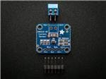
The INA219B breakout board can measure both the high side voltage and DC current draw over I2C with 1% precision and help in solving the power-monitoring problems.
Project info
Difficulty: Easy
Platforms: Arduino, Atmel, Microchip
Estimated time: 1 hour
License: MIT license (MIT)
Items used in this project
Hardware components
Story
In many applications we need to monitor both voltage and current of certain device in real time. To solve this problem, first thing that will come into ones mind is, use voltage sensor to measure voltage and current sensor for current. Or built a voltage divider for voltage and add a small resistor in current path and measure the voltage across that resistor to get current using V=IR (ohm's law).
In both cases if we use a high side sensor/circuit then we will lose resolution while measuring low side values. To solve such problems instead of using two different sensors/circuits we can use INA219. It has both current and voltage sensors with programmable gain amplifier which enable us to measure high and low side values with pretty good resolution.
In order to use INA219 module with AVR iot WG we need c library to make our life easier (available HERE). Create new project for AVR iot WG using Atmel Start.
Create New Project Using Atmel Start
Step 1: Go to Atmel Start and select "create new project"

Step 2: Search for AVR iot. Select "ATmega 4808 AVR IoT WG" and Create New Project.

Step 3: Select "My Project" and rename the project by selecting "Rename Component".

Step 4: New dialog box will open with project name. Rename it to "INA219" and select "Rename".

Step 5: After renaming the project "Add software component"
Step 6: Expand "Drivers" and select "I2C" and "USART" then select "Add component(s)".

Step 7: Select "USART_0" new related information will appear. Select "USART2" instance as shown below and make sure RXD and TXD pins are PF1 and PF0 respectively. Also check the "Printf Support" check box. Modify the baud rate if necessary.

Step 8: After modifying the USART setting, select "I2C_0" and select SDA - PA2 and SCL - PA3 and leave the rest as shown below.

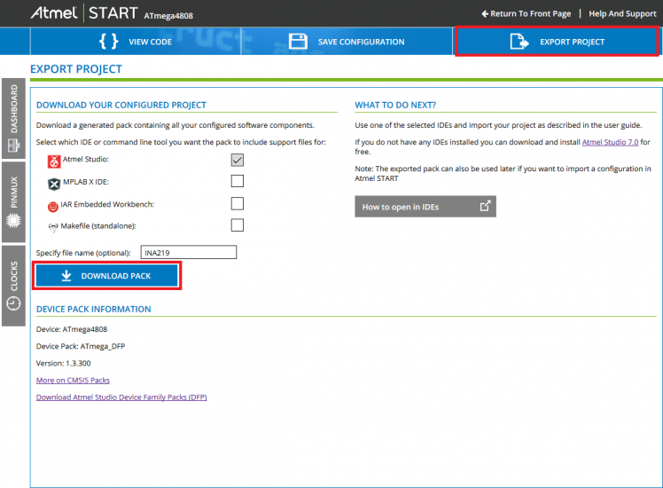
Step 9:Finally Select "Export Project" from top menu bar and assign the name to download file (optional) and select "Download Pack".
After creating a new project pack using Atmel Start online tool, open the downloaded file in Atmel 7 and select the project location and click open. Now download the INA219 c library from HERE and add into Atmel Project by right clicking on our project in "Solution Explorer" window and selecting "ADD" -- "Existing Item...". Choose both easyINA219.c and easyINA219.h files.

Enabling Floating Point Support for printf
By default printf command in Atmel Studio 7 doesn't print floating point (detailed tutorial HERE). To enable it press "ALT+F7" or goto "Project Properties" from "Project" menu. In project properties window select "Toolchain" then "AVR/GNU Linker".
In AVR/GNU Linker general setting enable "Use vprintf library(-WI,-u,vfprintf)" by checking the box as shown below.

Next step is go to AVR/GNU linker "Miscellaneous" settings and enter "-lprintf_flt" as shown below and save the project.

In the Last Step replace the "main.c" code with the following code.
- #include <atmel_start.h>
- #include "clock_config.h"
- #include <util/delay.h>
- #include "easyINA219.h"
- easy_INA219 ina219;
- int main(void)
- {
- /* Initializes MCU, drivers and middleware */
- atmel_start_init();
- sei();
- /* Replace with your application code */
- ina219.ina219_i2caddr=INA219_ADDRESS;
- ina219_begin(&ina219);
- ina219_setCalibration_16V_400mA(&ina219);
- float shuntvoltage = 0;
- float busvoltage = 0;
- float current_mA = 0;
- float loadvoltage = 0;
- float power_mW = 0;
- while (1) {
- shuntvoltage = ina219_getShuntVoltage_mV(&ina219);
- busvoltage = ina219_getBusVoltage_V(&ina219);
- current_mA = ina219_getCurrent_mA(&ina219);
- power_mW = ina219_getPower_mW(&ina219);
- loadvoltage = busvoltage + (shuntvoltage / 1000);
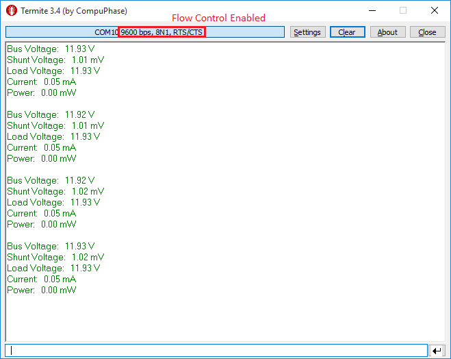
- printf("Bus Voltage: %.2f Vrn", busvoltage);
- printf("Shunt Voltage: %.2f mVrn", shuntvoltage);
- printf("Load Voltage: %.2f Vrn", loadvoltage);
- printf("Current: %.2f mArn", current_mA);
- printf("Power: %.2f mWrnrn", power_mW);
- _delay_ms(1000);
- }
- }
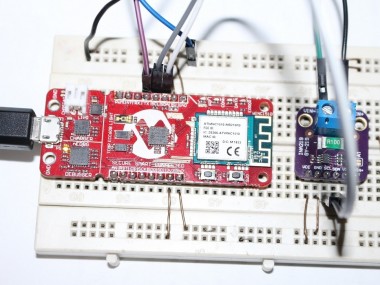
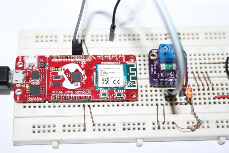
Now connect the INA219 module with AVR iot WG board as shown in schematic attached below. Build and upload the code to start measuring the current and voltages.
Schematics, diagrams and documents
Code
Credits
mahmood_ul_hassan
Electronics Engineer with specialization in Robotics Engineering, seven years of experience in electronics research and development. I worked mostly on designing custom labview based automatic test and measurement equipment. Hobbyist, ARM enthusiast, DIY maker
Related products


Leave your feedback...