

Drone Landing Pad With Arduino Timer

Made by DIY-Machines / 3D Printing / Drones / Games & Gaming / Robotics / Sensors
About the project
A drone landing pad with an integrated ultrasonic sensor that detects a drones presence and automatically times your laps.
Project info
Difficulty: Moderate
Platforms: Arduino
Estimated time: 2 days
License: GNU General Public License, version 3 or later (GPL3+)
Items used in this project
Hardware components


Story
I've been growing more and more interested in the idea of First Person Video (FPV) drone racing. I've recently acquired a small drone and wanted a way of timing my laps - this is the resulting project.
This drone landing pad features an integrated ultrasonic sensor that detects a drones presence. When a drone departs the Arduino starts a timer. When you return your lap time is displayed to you.
You can either try to improve your personal best or challenge a friend to do better than you (if you trust them with your drone that is).
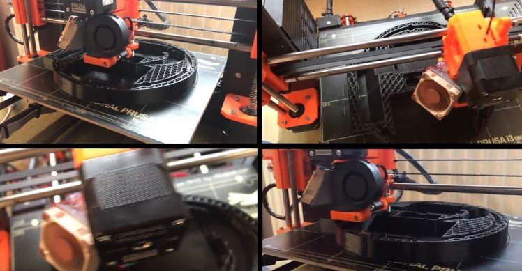
It can be printed and assembled over a couple of day including the required printing time.Here is a video guide explaining how to assemble the project.
You can download the 3D cad parts from Thingiverse.
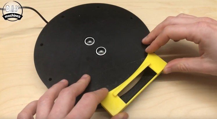
You'll need to start by printing the main base. I printed mine in black to match the colour of the ultrasonic sensor.
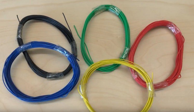
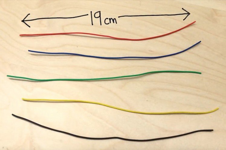
I'm using five colours of wire during this build, Black, Green, Red, Yellow and Blue. If you can use the same colours then you will find it much easier to follow along - but you can still build one with just a single colour of wire.
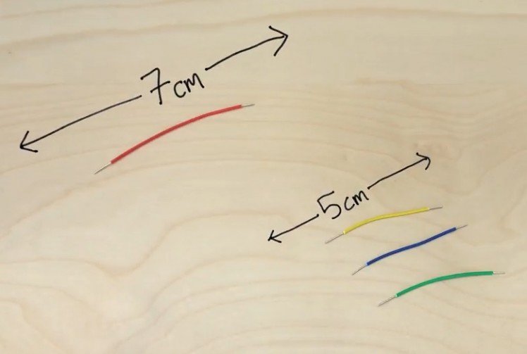
First cut one length of red at 7cm long and a 5cm length in yellow, blue and green.
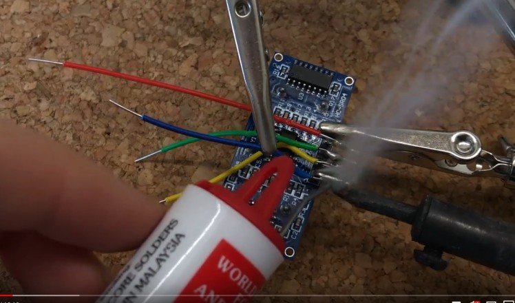
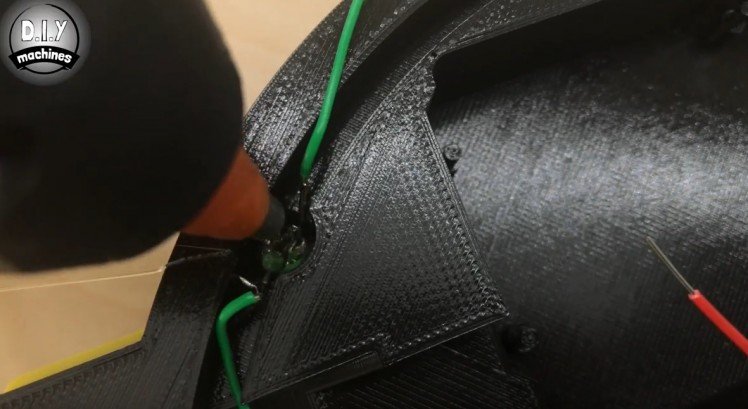
You will need to solder these on in the opposite direction then you would normally (take a look at the image above to see what I mean). They should be soldered as follows:
- Red --> VCC
- Green --> Trig
- Yellow --> Echo
- Blue --> Ground
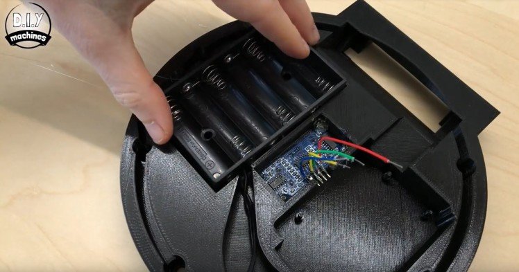
Once this is done you can glue it in place using some hot melt glue. At the same time, we can glue in place the battery holder.
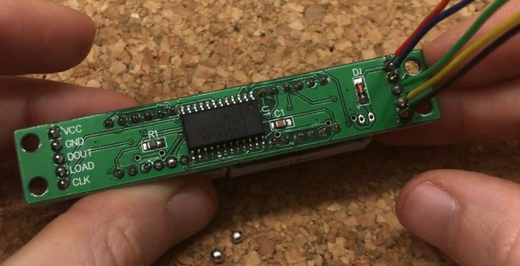
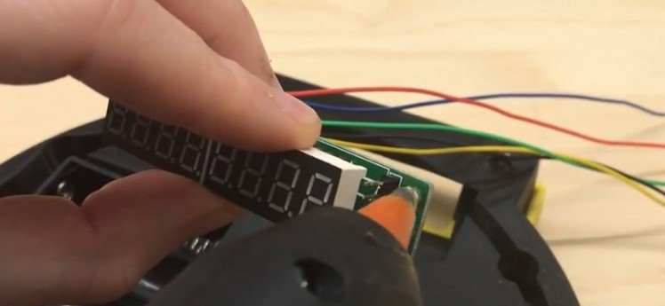
Now you need 5 wires, one of each colour cut to 19cm in length. You'll need to expose a bit more of one end of each wire as one end will be soldered to the display whilst the other will be pushed directly into the headers of the Arduino to cut down on the amount of soldering required.
They will be soldered to the rear side of the display on the points indicated below:
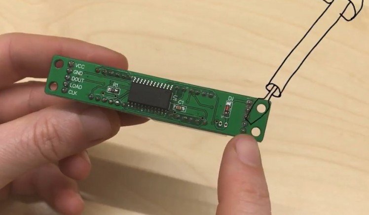
You need to solder them on in the order shown here:
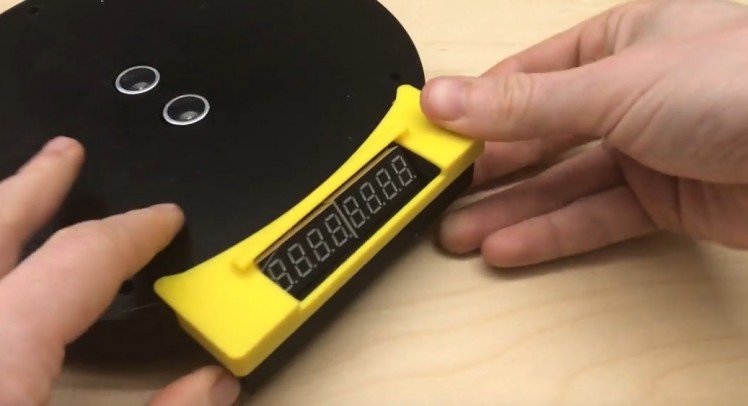
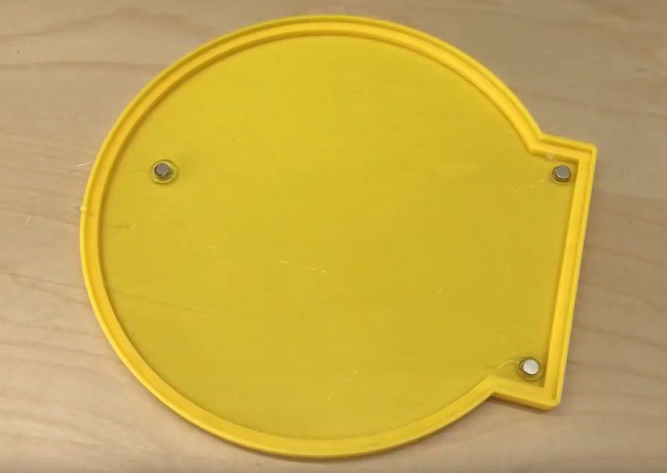
Next, print the shield for the screen. I chose to print mine in bright yellow to contrast with the black whilst also making it easier to see from your drones camera when you try to land on it.You attach this with some more hot melt glue.
You can also glue the seven segment display in place, this is also done with the trusty old hot melt glue gun. Use a little on each corner of the board and then insert from the underside of the base. Ensure that when you flip the base over and view it from the front, the decimal places are on the bottom of the display - if not then you're about to insert upside down!
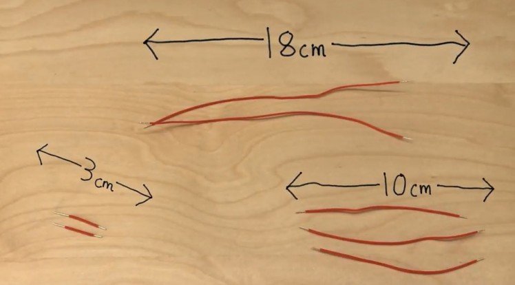
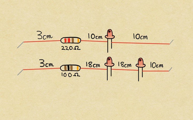
You now need the following wires which will connect along with the LED's and resistors to create the two strings of Green LEDs:
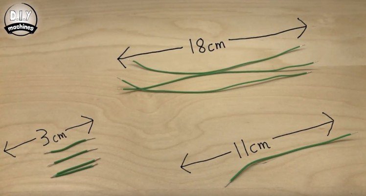
They then need soldering together with four green 5mm LEDs and two 100 Ohms resistors. Their colour markings go Brown-Black-Brown and then Gold at the end.
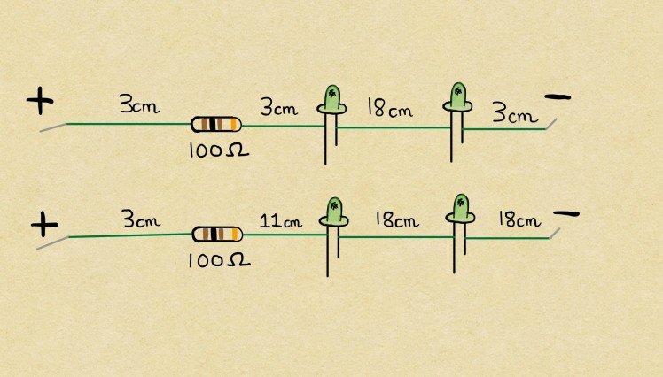
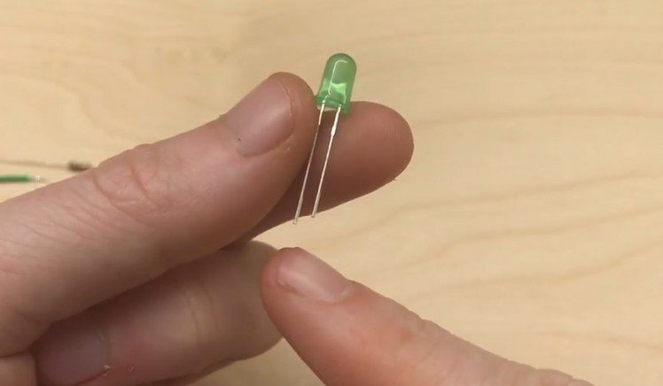
Make sure that the positive side of the LED (the longer leg) is connected to the positive side of the circuit. As current will only flow one way through an LED you'll find it won't work if one is attached the incorrect way.
Once you have soldered them together we will add them to the main base. Make sure the end of the wire with the resistor is closest to the display and push the first LED through the first hole going clockwise around the display. Then skip the next hole, and push the second LED through the proceeding hole.
You can then use some hot melt glue to hold the LEDs in position from behind whilst also ensuring the two legs of each LED don't come in contact with one another and shorten the circuit.
Repeat the same steps for the second string of LEDs but this time going anticlockwise from the display like this:
And then again backfill the LEDs with some hot melt glue.Now we will work on the red LEDs, you'll need to prepare another set of wires, 3 red LEDs, 1 x 100Ohm resistor, and 1 x 220 Ohm resistor. Attach them again as follow.
First we will add the string with a single LED in it. This wants to be added again with the resistor nearest the display plugging the gap when we work clockwise around the base. Don't forget to add some glue.
The string with two wants to go around in the other direction.
Glue three of the neodymium magnets to the base in the three pre-marked locations.
On top of the three magnets you glued in, allow three more to locate themselves. Then with a pen put a black dot on each so we can remember its polarity.
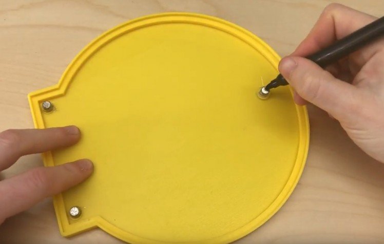
Once they are marked remove them but keep them in the same layout.
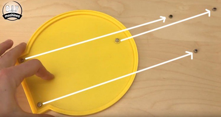
Now we will glue them into the main base, make sure you pay attention to where the two nearest the display switch positions. We also need to glue them in with the black marks we made earlier facing down. (So that when we have completed this step the black marks are buried into the printed base.)
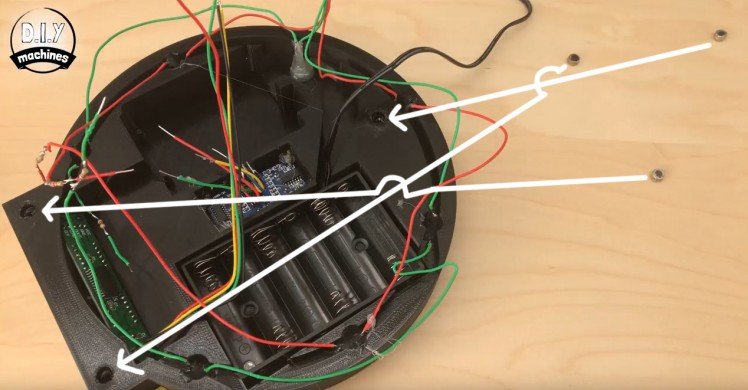
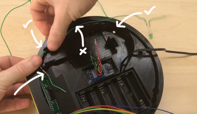
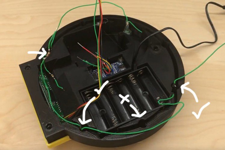
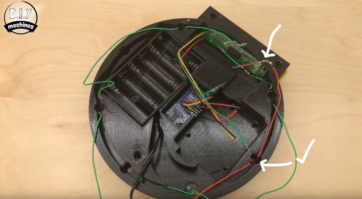
Take the four negative ends of the LED strings we glued in place earlier and solder them all to a single earth wire. I used a blue wire about 5cm long. This is they can all be connected to a single ground connection on the Arduino.
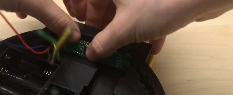
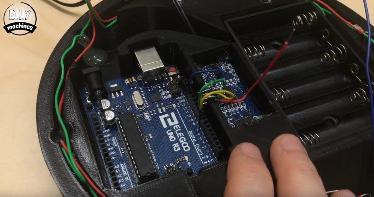
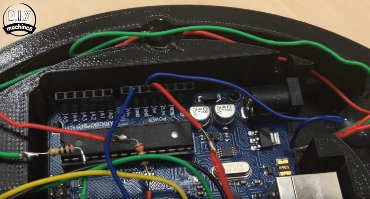
Now connect your Arduino Uno to your computer and upload the code you'll find towards the end of this article. Once this is don't you can disconnect it from your computer.

You can drop the Arduino into its resting place. There are pins that fit through the screw mounting holes on the Arduino board.
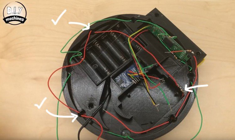
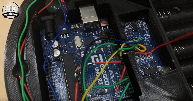
First we will connect three of the wires from the Ultrasonic sensor. Connect them as follows:
- Blue ground wire --> Ground
- Green Trig wire --> Pin 9
- Yellow echo wire --> Pin 8.
The red wire will be connected later.
Now the wires from the LEDs will connected like this:
- Blue earth wire --> Ground
- First green wire --> Pin 3
- Second green wire --> Pin 2
- First red wire --> Pin 6
- Second red wire --> Pin 7

Next is the display wires like this:
- Grey Clk wire --> Pin 13
- Green Din wire --> Pin 11
- Yellow CS wire --> Pin 10
- Blue Grnd wire --> Ground pin
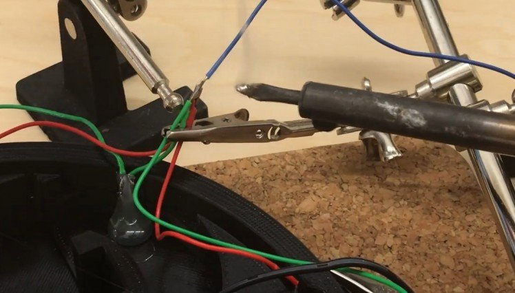
Again will be doing the red VCC wire next.
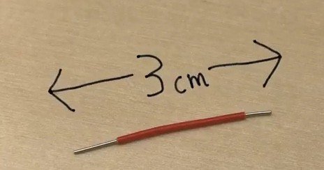
Cut a short length of red wire.
And use this to connect the two red VCC wires form the Ultrasonic sensor and the display together. We have to do this as we have only one 5v supply on the Arduino board.
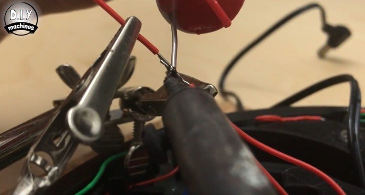
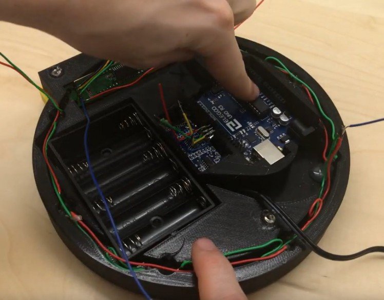
Now we can pop this in the 5v connection on the Arduino.
Print the top ring part and attach this as shown with some hot melt glue.
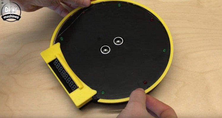
And that it, Voila! Add some batteries and take the skies. :)
Schematics, diagrams and documents
Code
Credits
Related products


Leave your feedback...