

Domestic Central Heating Radiator Efficiency Optimiser

Made by Al / Environmental Sensing / Home Automation / Sensors / IoT
About the project
IoT device to log input and output temperatures of a radiator. The plan is to get a display of temperature differential. One of the radiator valves can then be adjusted to change the water flow until an optimum drop is achieved. That is about 20F or 12C according to the Web, but Analytics on the data can help determine ideal.
Project info
Difficulty: Moderate
Platforms: Microchip
Estimated time: 1 hour
License: GNU General Public License, version 3 or later (GPL3+)
Items used in this project
Hardware components

Story
 It was supposed to take 30 seconds to get data into the Cloud from opening the dev board's box, but it took me over an hour just to get the demo software going! First I used an old (32-bit) laptop running Lubuntu. It seems that one needs to give the serial USB port ttyACM0 some kind of access rights but that is easily found online. Suffice to say words to the effect of 1. add user to dialup and 2. ensure read/write access. I tried to drag the hex file onto the USB port but with random success.
I tried on a Win10 machine and didn't have any major problems.
The board's instructions suggested 's' compile option but that is only available in the PRO version of the XC-8 compiler. The error/warning messages relating to that, and 'pragma pack', can all be ignored.
I used MPLAB's compile and program chip button and that worked perfectly.
Note that the two temp sensors only send in 1C increments. The maximum resolution is 0.166C per step and it is easy to change the software. These appear in the Cloud.
The clever bit (which I have not done!) is to do analytics on the Cloud data. It can work out things like boiler on/off times, U-value of the room, room ambient temp and radiator differential temperature. All it needs is a web feed of outside air temp, maybe from a weather station nearby.
Brief instructions:
Download and install MPLAB-X V5.10, then do the same for the XC-8 C compiler V2.05. These are the latest as of January 2019. In MPLAB, install the MCC plugin (v3.66 or later) from the Tools menu.Note that I am using Win10 on this 8-core PC. The procedure for Linux is slightly different in that the USB comms porthas to be added to dialup and chmod set correctly; most Linux users will know that already.
Select File/New Project, and enter the AVR4808 processor from the drop-down menu under AVR. Select Tool/Alternate Tools/nEDBG. Click on XC8(v2.05) in the Select Compiler menu.Instead of downloading source code from a repository such as GitHub, the source code is loaded by MPLAB as if by magic!
Click MCC. The CPU will then ask if you wish to save MyConfig in the project directory. Click OK.The interesting section is the lower left panel Versions. Select Libraries/Microchip Technology, Inc./Microcontrollers and Peripherals/AVR-IoT WG Sensor Node.It should display Library version 1.0.3 [Available for download.] (green tick) Library version 1.0.0 [C:Users..mcclibrariesavrIoT-v1.0.0.jar]
Double-click the top one and it will a) be highlighted and b) a tab comes up next to Versions saying Load Selected Libraries.Click the new tab.
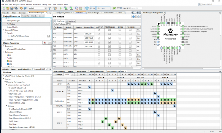
The pin view will be displayed with most pins blue which indicates unassigned. The next panel up, Device Resources, has a menu item at the bottom called Internet Of Things. You may need to scroll down the panel to find it and click it.It then displays Examples and Libraries.Examples has one entry: AVR-IoT WG Sensor Node. Double-click and the pins and internal peripherals will be assigned and set up.Double-click WINC in Project Resources/Internet Of Things/Libraries. You can change the SSID and password to match your network....make alterations...
Click the Generate tab in the top panel Project Resources. This process takes about 30 secondsPlug in board. Right click the Project and select Properties.Click on Conf:[default] to highlight it.Under Hardware Tools will appear AVR-0IoT WG (nEDBG) with its serial number underneath SN: ATML3202...Click XC8 Compiler, Optiion categories: Optimizations.The instructions from Microchip tell you to select level 's', but this only works for the paid-for PRO compiler.Use level 's' or '1'. Apply. OK.Optionally Click MCC to close it.A picture of the board appears in the main panel under Xplained Window.
Click the hammer icon. This takes about 11 seconds.
This is where it gets interesting. If you forget to set the optimization level, or you have another issue such as not plugging in the board, you end up with pages of red error messages.In fact even when optimize is set, there are loads of warning messages saying: #pragma pack( push, ATCAPacket, 2 ) and #pragma pack( pop, ATCAPacket).
I also found that the file i2c_simple_master.h 'did not exist' or could not be found, and the warning# warning "Compiler optimizations disabled; functions from <util/delay.h> won't work as designed",when I attempted to build a system without plugging in the board at some stage, or not optimzed, respectively.The latter is due to __OPTIMIZE__ undefined. There is probably a spare timer module that could be used to generate delays.
If all goes well, under Optimize level 1, I get Data Used at 36% and Program Used of 93%. That doesn't leave much room for additional features. Optimize level 's' comes up with loads of warnings about Compiler option (Optimize for size) ignored, but Program Used is a lower 92%!
In fact the Dashboard pane says Program Memory 4,310 bytes free. A bit tight!
The board can be unplugged and all is well; the source can be modified and the Build command (the Hammer) run. So back into MCC.
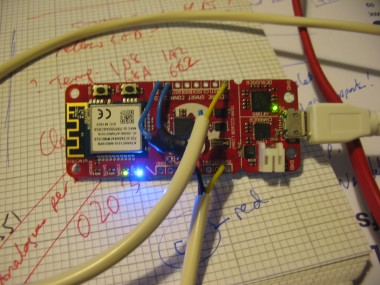
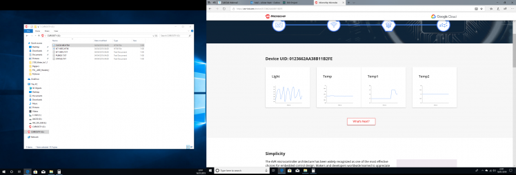
Plug board in and press build and program chip icon.After a few seconds you should see all leds blink in sequence, then blue and green come up. Finally an orange flash every second.Double-click CLICK-ME.HTM on the Curiosity Drive (G: on my Win10 PC).This link points to https://avr-iot.com/device/[a large hex number], and is the sandbox of a server somewhere in central USA.Graphs automatically display the last data, which in the case of the demo project, is light and board temperature.
While the board is connected via USB, and running, the monitor port may be tested at this point.I use RealTerm, but other terminal emulators are available. Select 9,600Bd and Port USBSER000.The AVR-IoT board does not echo characters back. Type key followed by Enter, and you should be rewarded with----BEGIN PUBLIC KEY------crlfThe key...(128 characters)...crlf----END PUBLIC KEY------crlf
version produces v1.0.3 andcli_version returns v2.0
debug 4 returns OK. But that's all, there is no debug info.
Software mods:
// Radiator feed INLET sensor: Connect MCP7901AE to AIN = PD7// Radiator feed OUTLET sensor: Connect MCP7901AE to INT = PD6
Note: I have made slight additions to the example code 'Internet of Things->Examples->AVR-IoT WG Sensor Node'.
- Sensors_handling.h
- #ifndef SENSORS_HANDLING_H
- #define SENSORS_HANDLING_H
- uint16_t SENSORS_getLightValue(void);
- int16_t SENSORS_getTempValue (void);
- uint16_t SENSORS_getTemp1Value(void);
- uint16_t SENSORS_getTemp2Value(void);
- #endif /* SENSORS_HANDLING_H*/
- // sensors_handling.c
- #include <stdint.h>
- #include "sensors_handling.h"
- #include "include/adc0.h"
- #include "include/i2c_simple_master.h"
- #define MCP9809_ADDR 0x18
- #define MCP9808_REG_TA 0x05
- #define LIGHT_SENSOR_ADC_CHANNEL 5
- // APRW
- // INPUT sensor: Connect MCP7901AE to AIN = PD7
- // OUTPUT sensor: Connect MCP7901AE to INT = PD6
- #define TEMP1_SENSOR_ADC_CHANNEL 7
- #define TEMP2_SENSOR_ADC_CHANNEL 6
- uint16_t SENSORS_getLightValue(void)
- {
- return ADC_0_get_conversion(LIGHT_SENSOR_ADC_CHANNEL);
- }
- uint16_t SENSORS_getTemp1Value(void)
- {
- return ADC_0_get_conversion(TEMP1_SENSOR_ADC_CHANNEL);
- }
- uint16_t SENSORS_getTemp2Value(void)
- {
- return ADC_0_get_conversion(TEMP2_SENSOR_ADC_CHANNEL);
- }
- int16_t SENSORS_getTempValue (void)
- {
- int32_t temperature;
- temperature = I2C_0_read2ByteRegister(MCP9809_ADDR, MCP9808_REG_TA);
- temperature = temperature << 19;
- temperature = temperature >> 19;
- temperature *= 100;
- temperature /= 16;
- return temperature;
- }
- // main.c
- #include <stdio.h>
- #include <string.h>
- #include <stdlib.h>
- #include "mcc_generated_files/application_manager.h"
- #include "mcc_generated_files/led.h"
- #include "mcc_generated_files/sensors_handling.h"
- #include "mcc_generated_files/cloud/cloud_service.h"
- // 400*1024/3300
- #define Offset0C 124
- // MCP9701A sensors connected to 0V, 3V3
- // and AIN for Input Temp1
- // and INT for Output Temp2
- int ConvMCP9701_to_temp(unsigned int Sensor)
- {
- int val;
- // MCP7901A has 19.5mV/C and zero offset of 400mV
- // assume ADC reference is 3.3V
- // ADC_REFSEL_VDDREF_gc
- // each bit is 3300/1024 mV = 3.22mV, (10 bits)
- // so each C is 6 bits.
- // 0C offset of 400mV is (400/3300)1024 bits = 124
- val= Sensor-Offset0C; // val = 0 at 0C
- return val/6; // output is in 1C steps
- }
- // This will get called every N seconds only while we have a valid Cloud connection
- void sendToCloud(void)
- {
- static char json[70];
- int T1C, T2C; // tenths of C, signed
- // This part runs every CFG_SEND_INTERVAL seconds
- int rawTemperature = SENSORS_getTempValue();
- unsigned int Temp1 = SENSORS_getTemp1Value();
- unsigned int Temp2 = SENSORS_getTemp2Value();
- int light = SENSORS_getLightValue();
- // APRW Add Temp1 and temp2: that works! 13-01-2019
- // convert Temp1/2 into C in steps of 1
- // Note that 91% of program memory is in use!
- T1C = ConvMCP9701_to_temp(Temp1);
- T2C = ConvMCP9701_to_temp(Temp2);
- int len = sprintf(json,
- "{"Light":%d,"Temp":"%d.%02d","Temp1":"%d","Temp2":"%d"}"
- ,light,rawTemperature/100,abs(rawTemperature)%100,
- T1C, T2C );
- if (len >0) {
- CLOUD_publishData((uint8_t*)json, len);
- }
- LED_flashYellow();
- }
- int main(void)
- {
- application_init();
- while (1)
- {
- runScheduler();
- }
- return 0;
- }
PD4, PD5 and PD7 are now analogue inputs.
Well, the deadline for submission now approaches at high speed (well, it's tomorrow to be specific) and I have done some further work in the three months or thereabouts since part I was written.
Part II...
I have tried making new MPLAB projects from scratch and get various problems. The last attempt to use XC8 gave an error 'device-specs/specs-atmega4808: no such file or directory. Incidentally the compiler comes up with zillions of warnings 'pragma pack has no effect with -fpack-struct - ignored [-Wpragmas].
I have not managed to fix those problems as the software seems to work. There are a lot of engineers out there who would try to resolve these warnings and either spend a lot of time doing so, or give up.
When using the XC8 compiler, there is a lower left pane, the Dashboard, that tells one how much RAM and ROM of used. There were only a few k bytes of ROM free. In fact the compiler has to use some sort of optimization otherwise it will not fit at all! Level 's' is ignored in the free version of the compiler, so I used level '1'.
After the last compile fail, I decided to try the AVR compiler. That still produces all those pragma pack warnings, but at least it compiled and linked. A swift SSID and Wi-Fi password change to conf-winc.h was made. I could have changed them in the MCC's WINC setup.
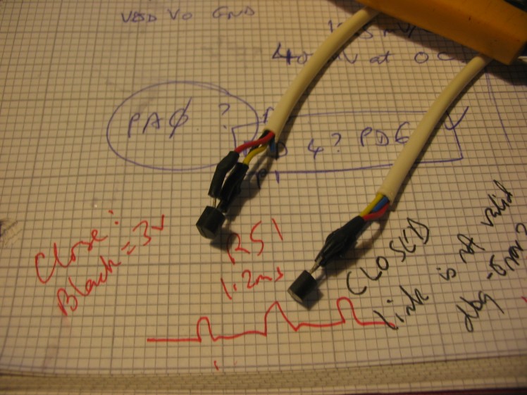
Now we have a working board which connects to the Cloud and displays graphs, it is time to add the two temperature sensors. The Microchip MCP9701 is very cost-effective and even cheaper than many thermistors ( depending on quality/quantity of course).
I have just added extra items to be sent in the JSON message: differential temp and length of the message. The message is 76 bytes in length. The reason that is there is purely to get an idea of how bloated this is. My last project was using LoRaWAN, where every single bit was not set unless vital; messages are kept as short as possible and 8 bytes was considered ideal. One base station could cover thousands of motes in a catchment area of 300 square kilometres, hence data collisions are a major concern. Fortunately, a home Wi-Fi router will only have a few hundred square metres of coverage and usually less than a dozen connected devices, so the rules are different.
Oh yes, I remember now, the reason to find the message size is to determine costs for a Cloud service. Costs seem to depend on data throughput. For another project I would like to send short (10 second) segments of audio and maybe some bright spark will let me know how to do this in MQTT and/or JSON ;-)
A further addition is 32-entry circular buffers for the radiator sensors and differential temp.
This is so data need not be sent if the differential is zero, to minimise any costs.
Talking of costs, I really wanted to try and connect this board to my own server that can run on this PC. The server is written in about 20 lines of Python, and stores incoming TCP/IP messages in a file, using the static IP address and a fixed Port, using BSD Sockets. This is cost-free and I can send loads of data without worrying.
I have not been able to make this board do that. Again, a bright spark may be able to tell me how to do that ;-)
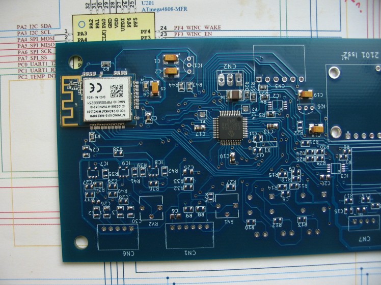
The WG name means Wi-Fi Google. I discovered that yesterday! So it looks as if there is some hard coding going on. To get round this, and also the fact that there is only 4,310 bytes of Program Memory free, I built my own board with a larger capacity PIC, a PIC24FJ256GA705. But unfortunately I have not managed to get the SPI comms working properly except once when I go a sign-on message back. The 'legs' on the PIC are pitched at 0.5mm and the ATWINC1510 legs are larger but not ideal for soldering test probes on. In case my RF module was intermittent, I bought another dev board: the PIC-IoT WG. This has a PIC24FJ128GA705 instead of the AVR. I have yet to get this to work in TCP/IP and Port socket mode, any bright sparks out there?
There is plenty of example software, but not all examples compile and/or they need a fair bit of help. Furthermore, the following
1. MCC. This has a useful-looking WINC Easy Setup where the SSID, security method and password can be entered. But loading it into a new project on its own seems to cause compile issues with 'not found' errors.
2. ASF. This is the Atmel Studio 7 software framework for sample code, but seems to be AVR-oriented.
3. Microchip Harmony. For 32-bit devices, so no good for the extreme low power 24FJ.
4. Microchip MLA. Used with MPLAB-X but I am not sure how it compares to MCC. Again, any bright sparks out there or is Cartman from MCHP's Forum watching ;-)
Yesterday I go a board partially soldered up with a new PIC and ATWINC1510 to see if that is any more reliable. But I have yet to solder on a 3.3V LDO regulator ( MCP1700 in TO-92)
Here is the new PIC board...PIC24FJ256GA705 and WINC1510
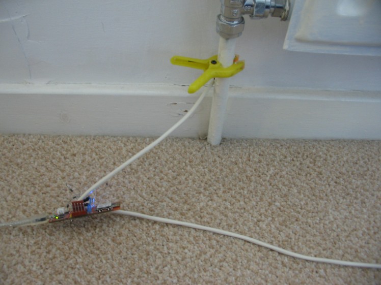 Inlet side of the radiator
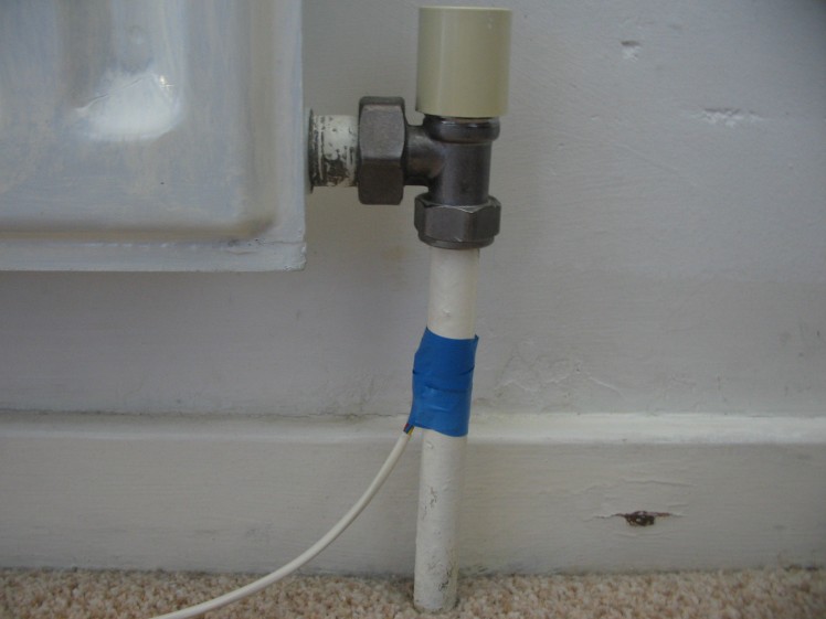 Outlet side. I could not find another plastic clamp so used blue insulating tape. Wooden clothes pegs do not open up enough.
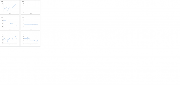
The results, using a 5 second update rate. Note that the Light is dropping because this is late afternoon. Differential reaches about 8C.
Schematics, diagrams and documents
Code
Credits
Al
Been a keen radio amateur for many years. HF CW activity when I get the chance...homebrew radios and gadgets from valve amplifiers using EL84s etc in the past to a TV sound-bar using an Arduino and Class-D amplifier. I have been trying to build an electronic organ for a while but technology changes before I get anywhere!
Related products


Leave your feedback...