
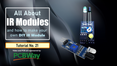
Diy - Ir Module

Made by tarantula3 / Environmental Sensing / Home Automation / Robotics / Sensors / IoT
About the project
In this tutorial, we are going to talk about "IR sensors" or Infrared sensors, how they work and how to build a "DIY IR Sensor Module".
Project info
Difficulty: Easy
Platforms: Adafruit, Arduino, Blynk, Google, Idiotware Shield
Estimated time: 1 hour
License: GNU General Public License, version 3 or later (GPL3+)
Items used in this project
Hardware components

|
LM358 IC | x 1 | |
|
|
10K Potentiometer | x 1 | |
|
|
LED | x 1 | |
|
|
IR LED | x 1 | |
|
|
PhotoDiode | x 1 | |
|
|
100Ω Resistor | x 1 | |
|
|
100kΩ Resistor | x 1 | |
|
|
220Ω Resistor | x 1 |
View all
Story
DIY - IR Module
A sensor is a device that detects and responds to inputs from the physical environment. The input can be light, heat, motion, moisture, pressure, or any other environmental phenomena. Sensors are very important part of electronics, especially in Robotics and Automations. The output generated by the sensors are transmitted to other circuits for reading or for further processing. They make our life easy by automatically sensing and controlling devices, without human interaction. In this video, we are going to talk about "IR sensors" or Infrared sensors, how they work and how to build a "DIY IR Sensor Module".Components Used
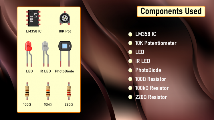 For this project we need:
- 1 x LM358 IC
- 1 x 10K Potentiometer
- 1 x LED
- 1 x IR LED
- 1 x PhotoDiode
- 1 x 100Ω Resistor
- 1 x 100kΩ Resistor
- 1 x 220Ω Resistor
IR LED
Now lets talk about the three main components of this module:1. IR Transmitter [IR LED]
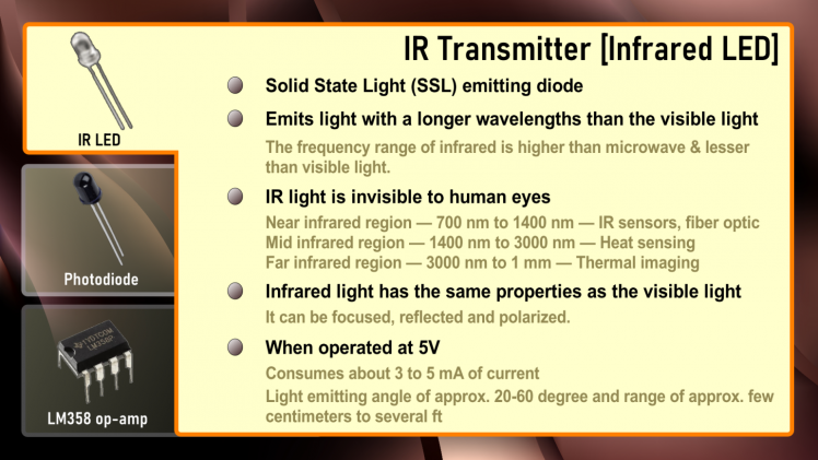 The IR LED (Infrared Light-Emitting Diode) is a SSL (Solid State Light) emitting diode that emits light with a longer wavelengths than the visible light. (The frequency range of infrared is higher than microwave and lesser than visible light). IR light is invisible to human eyes as its wavelength ranges between 700nm to 1mm. Everything which produce heat, emits infrared light, a very common example is the human body and fire. Infrared light has the same properties as the visible light, it can be focused, reflected and polarized. The appearance and operation of an IR LED is same as a common LED. When operated at 5V, the IR transmitter consumes about 3 to 5 mA of current. Depending upon the Transmitter and Manufacturer, IR LEDs can have light emitting angle of approx. 20-60 degree and range of approx. few centimeters to several ft (Some transmitters have the range in kilometers).Since the human eye cannot see the infrared radiations, it is not possible for a person to identify if an IR LED is working or not. The simplest way to view infrared light is by using a remote control while looking through a camera. If the infrared LED is working, it will appear on the digital camera's viewfinder as a purple glow.Unlike LEDs that project parts of the visible light spectrum, IR LEDs are not used to provide lighting. They are, instead, most commonly used in various signal transferring systems, such as in remote controls, night-vision cameras and other devices.IR LED’s are commonly used in conjunction with the IR receiver to support a wireless communication between 2 or more devices.2. IR Receiver [PhotoDiode]
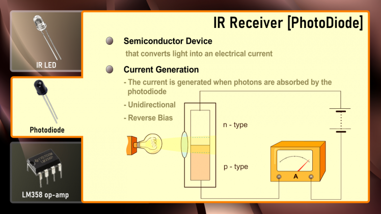
A photodiode is a semiconductor device that converts light into an electrical current. The current is generated when photons are absorbed by the photodiode similar to a Light Dependent Resistor (LDR), means it has very High Resistance in absence of light and the Resistance become low when light falls on it. However, unlike the LDR which is analogue and bidirectional, Photodiode is a unidirectional semiconductor which has a P-N junction and operates in Reverse Bias (means it start conducting the current in reverse direction when Light falls on it). Photodiodes can only do two values: either on or off.
Photodiodes also looks like a LED, with a Black color coating on its outer surface.Different types of IR receivers exist based on the wavelength, voltage, package, etc. When used in an infrared transmitter – receiver combination, the wavelength of the receiver should match that of the transmitter.
3. LM358 IC
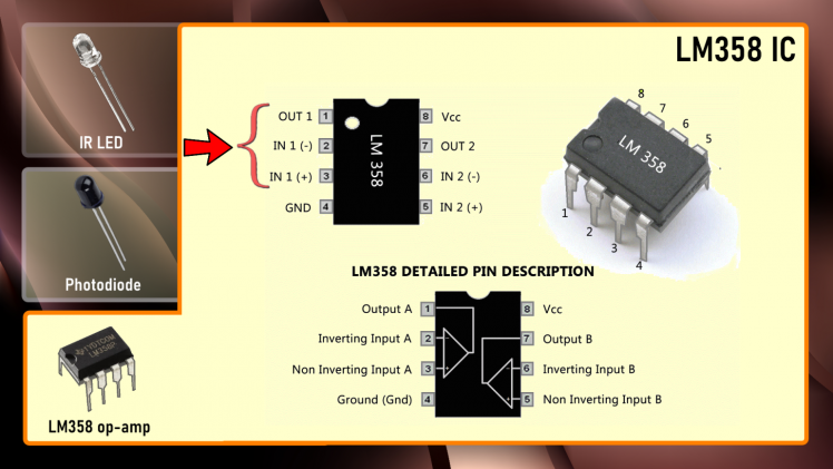 LM358 is a dual operational amplifier (Op-Amp) IC, integrated with two op-amps powered by a common power supply. In this circuit we are using it as a voltage comparator. The LM358 has two independent voltage comparators inside it, which can be powered by single pin, so we can actually build two IR sensor modules using this IC. In this tutorial I will only use one comparator, which have inputs at PIN 2 and 3 and output at PIN 1. The voltage comparator has two inputs, one is inverting input (PIN 2) and second is non-inverting or in-phase input (PIN 3). When voltage at non-inverting input (positive pin) is higher than the voltage at inverting input (negative pin), then the output of comparator (PIN 1) is High. And if the voltage of inverting input (negative pin) is Higher than non-inverting end (positive pin), then output is LOW. PIN 4 is the negative power supply (when dual power supply operates) or ground (when single power supply operates). PIN 8 is the positive power supply; Pins 1, 2, and 3 are one op-amp channel, and pins 5, 6, and 7 are the 2nd op-amp channel.
LM358 Datasheet: Download File
Principle of Working 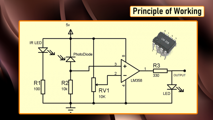
An IR sensor consists of an IR LED and a Photodiode (together they are called as Opto–Coupler or Photo–Coupler). IR sensor work on the principal in which IR LED emits infrared radiation and Photodiode sense that radiation. Photodiode's resistance changes according to the amount of IR radiation falling on it, hence the voltage drop across it also changes and by using a voltage comparator (like LM358) we can sense the voltage change and generate the output accordingly.We can place IR LED and Photodiode in two different ways: 1. Direct and2. IndirectIn Direct incidence, IR LED and photodiode are placed facing each other, so the IR radiation directly falls on the photodiode. When an object is placed between the IR pair, it stops the falling of IR light on the photodiode.And in Indirect Incidence, both IR LED and Photo diode are placed side by side (in parallel both facing the same direction). When an object is placed in front of IR pair, the IR light gets reflected by the object and gets absorbed by photodiode.Schema
Basically, an IR Module is a combination of a IR transmitter and receiver circuit.Infrared light emitted by the IR LED is detected by the Photodiode. LM358 Op–Amp IC is used as a voltage comparator. Voltage at inverting end, which is also called "Threshold Voltage", can be set by rotating the potentiometer.When we turn ON the circuit there is no IR radiation towards photodiode and the Output of the comparator is LOW. By placing an object in front of IR pair, we reflect the IR light which is absorbed by the photodiode and the voltage across photodiode drops, and the voltage across series resistor R2 increases. When the voltage at Resistor R2 (which is connected to the non-inverting end of comparator) gets higher than the voltage at inverting end, then the output becomes HIGH and LED turns ON.Voltage at inverting end, can be set by rotating the variable resistor’s knob. Higher the voltage at inverting end (-), less sensitive the sensor and Lower the voltage at inverting end (-), more sensitive the sensor. The threshold voltage can be adjusted by adjusting the potentiometer depending on the environmental conditions.
The Board
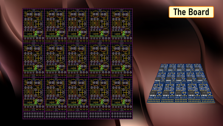 So, this is how my board looks like in 2D and 3D.There are 15 individual IR Modules on this 100cm x 100cm board.Gerber : Download File
Assembly 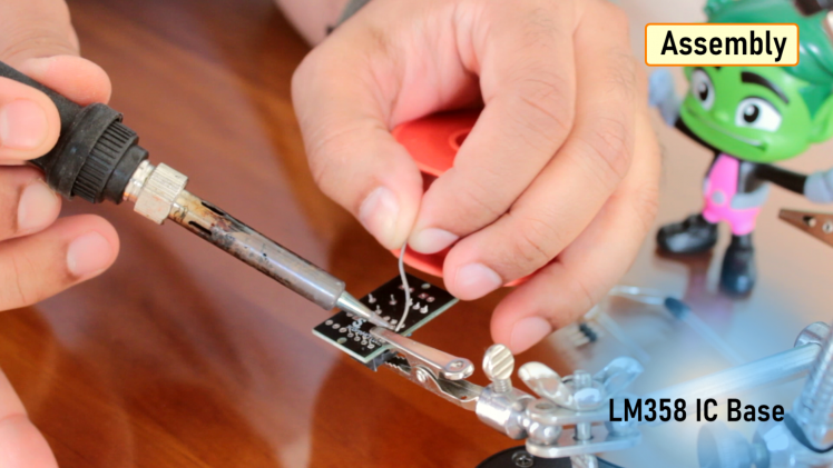 Lets start the project by soldering the 3 resistors to the board. After that, I am soldering the 10K pot followed by the base of the LM358 IC.Next, I am soldering the male pin header to the board. After that, I am soldering the optional LED indicator to the board. If you don't want the LED indicator then you can skip the 220Ω Resistor which we installed in Step 1.Next, I am soldering the photodiode and the IR LED to the board. Now, to finalize the setup I am installing the LM358 IC to the base which we soldered in Step 3, that's it all done.
Demo
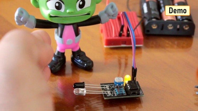 By placing my hand infront of the IR module I am reflecting the infrared light emitted by the IR LED towards the PhotoDiode. The PhotoDiode detects the light and turns the output of comparator PIN-1 to High. When the output at Pin-1 goes HIGH the LED indicator lights up.By adjusting the resistance of the potentiometer we can control the sensitivity of the phototransistor.Areas of Application
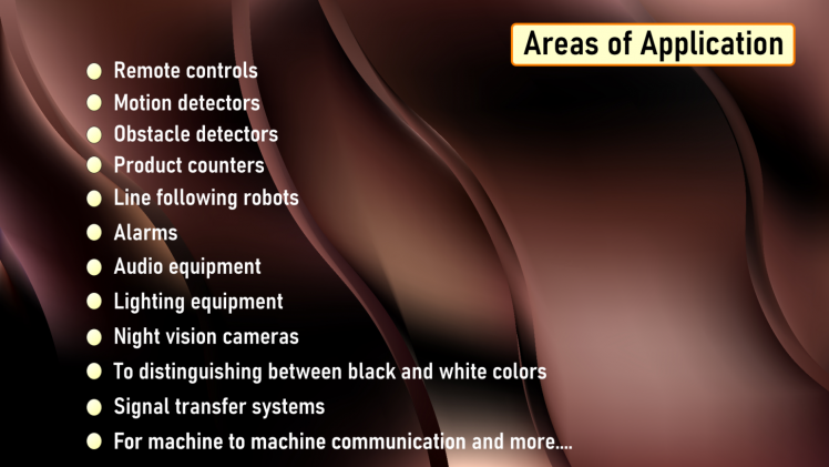 Advantages and Disadvantages
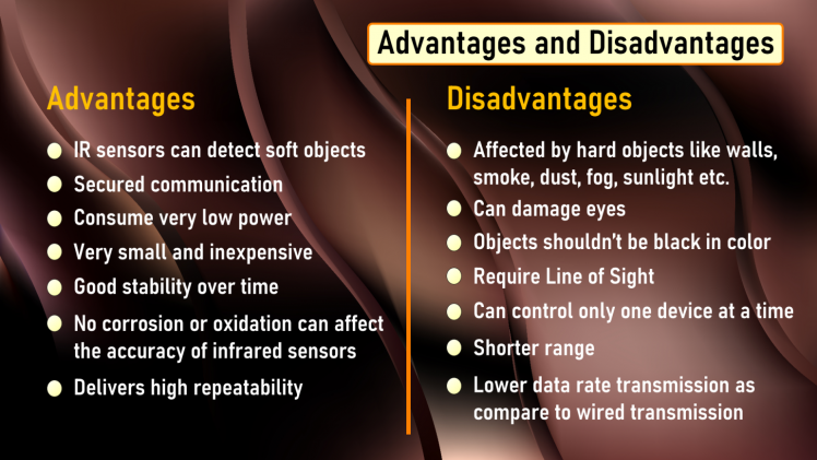
 Thanks
YouTube Channel: https://www.youtube.com/user/tarantula3Video: https://www.youtube.com/watch?v=_M8FQIPi1qkFull Blog Post: https://diyfactory007.blogspot.com/2020/10/diy-ir-module.html
Gerber File: https://drive.google.com/file/d/1mmgJSyBvGcu06svoI5GWUhi9RXikFYVA/view?usp=sharingLM358
Datasheet: https://drive.google.com/file/d/1xB7Pk_Mp4StcMPGTS2LTl527Tr1VT-Yb/view?usp=sharingBTC: 35ciN1Z49Y1bReX2U7Etd9hGPWzzzk8TzF
DOGE: DDe7Fws24zf7acZevoT8uERnmisiHwR5st
LTC: MQFkVkWimYngMwp5SMuSbMP4ADStjysstm
ETH: 0x939aa4e13ecb4b46663c8017986abc0d204cde60
BAT: 0x939aa4e13ecb4b46663c8017986abc0d204cde60Thanks, ca again in my next tutorial.
Credits
Related products


Leave your feedback...