
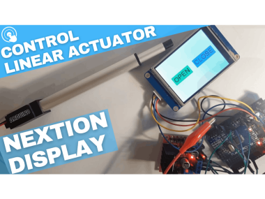
Control Linear Actuator Using A Nextion Display And Arduino

About the project
In this Project we will learn how to control a Linear Actuator with Nextion Display and Arduino. Watch the Video!
Items used in this project
Hardware components

Story
1 / 6

- Arduino UNO (Or any other Arduino)
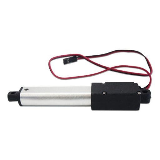
- Linear Actuator
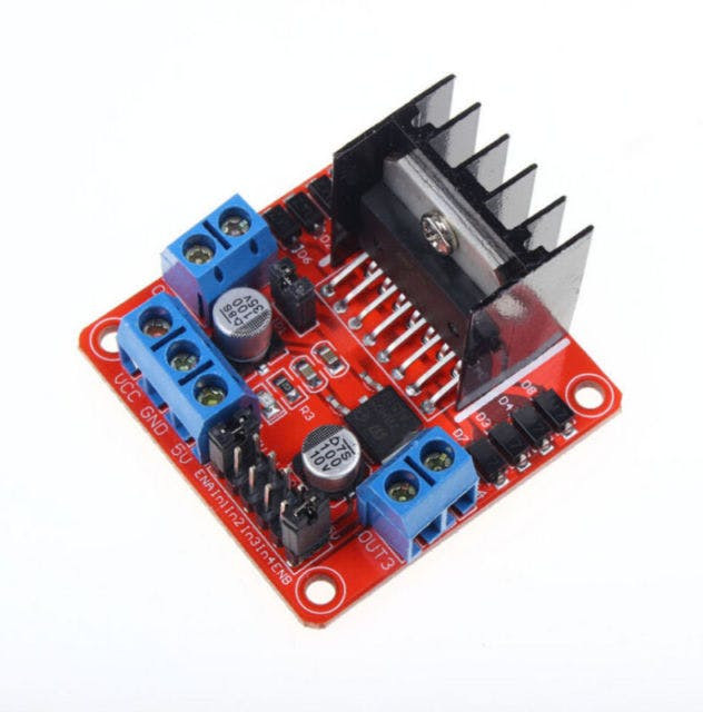
- LN298N DC Motor Driver
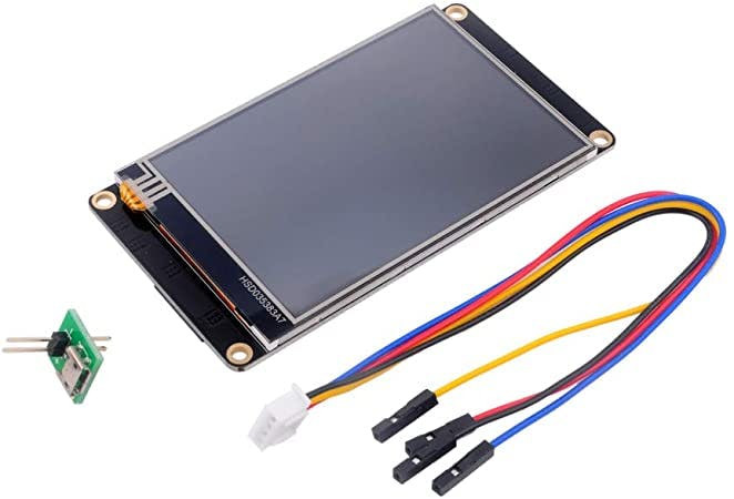
- Nextion Display
- Jumper wires
- Power Supply
- Nextion Editor: Download Nextion Editor
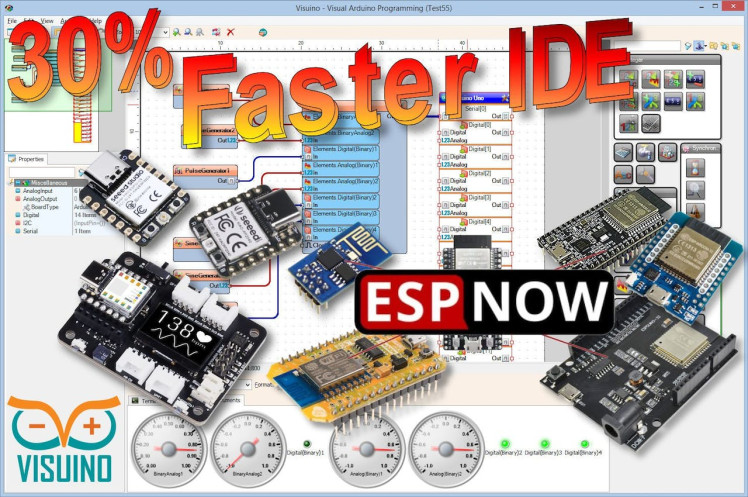
- Visuino program: Download Visuino
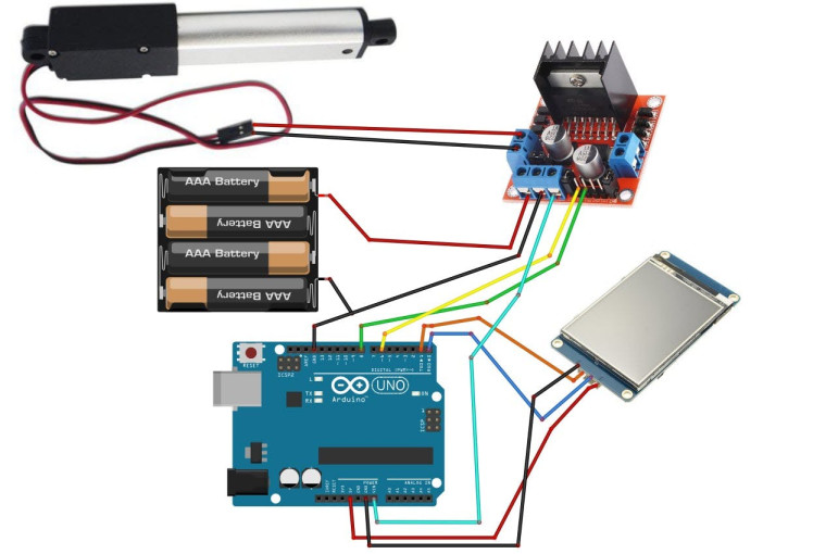
- Connect Power supply (batteries) pin (gnd) to motor driver controler pin (gnd)
- Connect Power supply (batteries) pin (+) to motor driver controler pin (+)
- Connect Power supply (batteries) pin (+) to Arduino pin (VIN)
- Connect GND from Arduino to motor driver controler pin (gnd)
- Connect digital pin(6) from Arduino to motor driver pin (IN1)
- Connect digital pin(8) from Arduino to motor driver pin (IN2)
- Connect Linear Actuator to the motor driver as you can see on the schematic
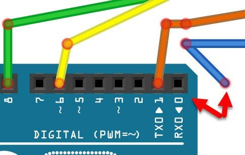
- Connect Nextion Display VCC red wire to Arduino 5V pin
- Connect Nextion Display GND black wire to Arduino GND pin
- Connect Nextion Display Yellow wire (RX) wire to Arduino TX pin
- Connect Nextion Display Blue wire (TX) wire to Arduino RX pin
1 / 12

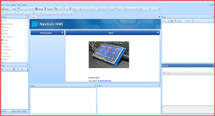
- Download Nextion Editor and Install it
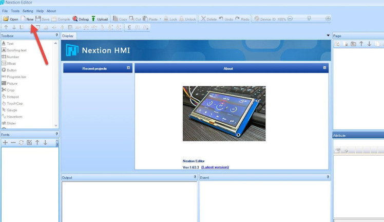
- Start Nextion Editor
- In the Nextion Editor click on the "New" button
- In the Window set the name for the Project like "ACTUATOR"
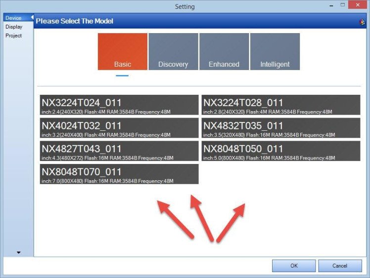
- In the "Setting" window select the Model of your Nextion Display & click "Ok"
- Select Display Direction 90 & click "Ok"
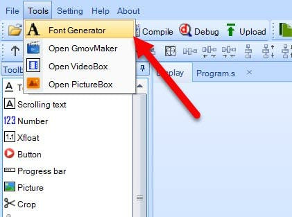
- In the Menu select "Tools">"Font Generator"
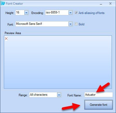
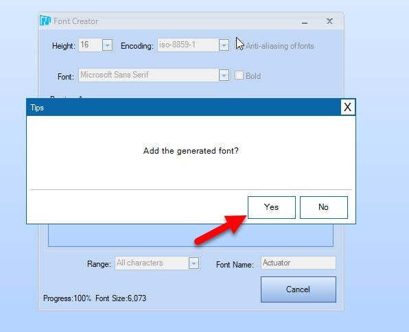
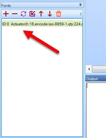
- In the Font creator window set the name for your font and click "Generate Font", Save the Font, you will be asked "Add the generated font?" Click Yes
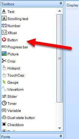
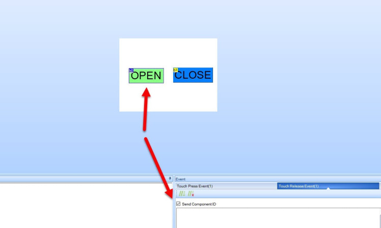
- In the Editor on the left in the "Toolbox" find "Button" & drag 2 Buttons it to the right
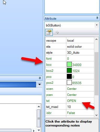
- For the first button Select it and in the "Attribute" window set "txt" to OPEN and "bco" to Green color
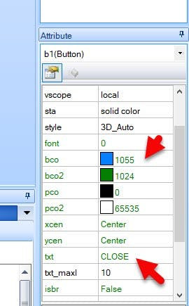
- For the second button Select it and in the "Attribute" window set "txt" to CLOSE and "bco" to Blue color
- For both buttons:
- In the "Event" window > Touch Press Event" Check the "Send component ID"
- In the "Event" window > Touch Release Event" Check the "Send component ID"
- In the Toolbar click on the "Compile" button
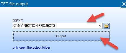
- In the Menu Select "File" > "TFT File Output"
- Set the Output folder & click on the "Output" button
- Save the File to the SD card
- Insert the SD card to your Nextion Display
- Power the Arduino and you will notice that the Nextion Display will start to Update it self
- On the Finish disconnect the power and remove the SD card from the Nextion display
1 / 2
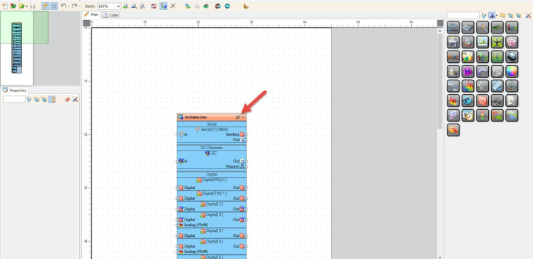
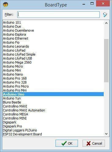
Start Visuino as shown in the first picture Click on the "Tools" button on the Arduino component (Picture 1) in Visuino When the dialog appears, select "Arduino UNO" as shown on Picture 2
Step 5: In Visuino Add, Set & Connect Components1 / 9
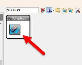

- Add "Nextion Display" component
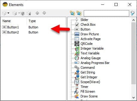
- Double click on the "DisplayNextion1" And in the Elements window drag "Button" to the left side.
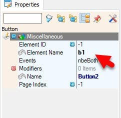
- Drag another "Button" to the Left side and in the properties window set "Element Name" to b1
- Close the Elements window
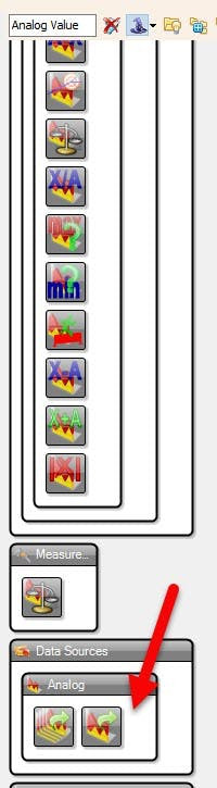
- Add "Analog Value" component
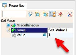
- Double click on the "AnalogValue1" and in the Elements window drag "Set Value" to the left side and in the properties window set "Value" to 1
- Drag another "Set Value" to the left side
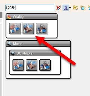
- Add "Dual DC Motor Driver Digital and PWM Pins Bridge (L9110S, L298N)" component
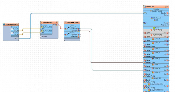
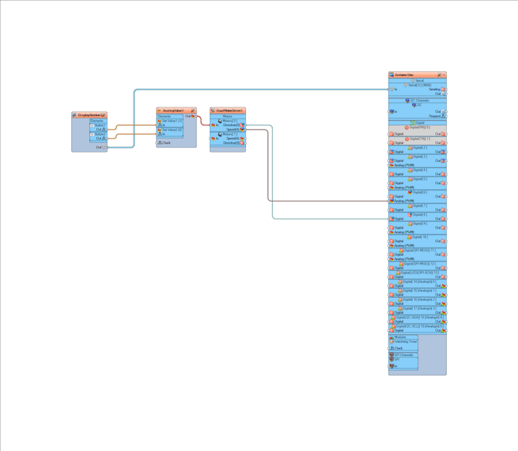
- Connect "DisplayNextion1" > "Button1" Pin[Out] to "AnalogValue1" > "Set Value1" pin [In]
- Connect "DisplayNextion1" > "Button1" Pin[Out] to "AnalogValue1" > "Set Value2" pin [In]
- Connect "DisplayNextion1" Pin[Out] to "Arduino" > "Serial [0]" pin [In]
- Connect AnalogValue1" pin[Out] to "DualMotorDriver1" > "Motors 0" > Pin [In]
- Connect "DualMotorDriver1" > "Motors 0" Pin [Direction] to Arduino digital pin [8]
- Connect "DualMotorDriver1" > "Motors 0" Pin [Speed] to Arduino digital pin > Analog PWM [6]
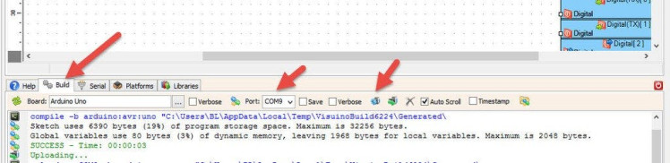
Before Uploading Disconnect RX pin on Arduino and connect it back after the Upload.
In Visuino, at the bottom click on the "Build" Tab, make sure the correct port is selected, then click on the "Compile/Build and Upload" button.
Step 7: PlayIf you power the Arduino module and press the on the button "OPEN" on the Nextion Display the Linear Actuator will start to move in one direction and if you press the button "CLOSE" on the Nextion Display the Linear Actuator will reverse.
Congratulations! You have completed your project with Visuino. Also attached is the Visuino project, that I created for this Project, you can download it here and open it in Visuino: https://www.visuino.eu
Schematics, diagrams and documents
Code
Credits
Related products


Leave your feedback...