
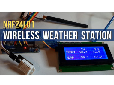
Arduino Wireless Weather Station Using Nrf24l01, Dht11-dht22

Made by Ron / Communication / Environmental Sensing / Garden / Home Automation / Weather
About the project
Build a wireless weather station using two NRF24L01 modules that will Display both Indoor and Outdoor Temperature & Humidity.
Items used in this project
Hardware components

Story
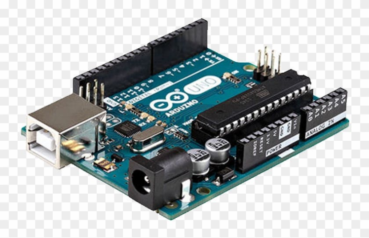
- 2X Arduino UNO (or any other Arduino)
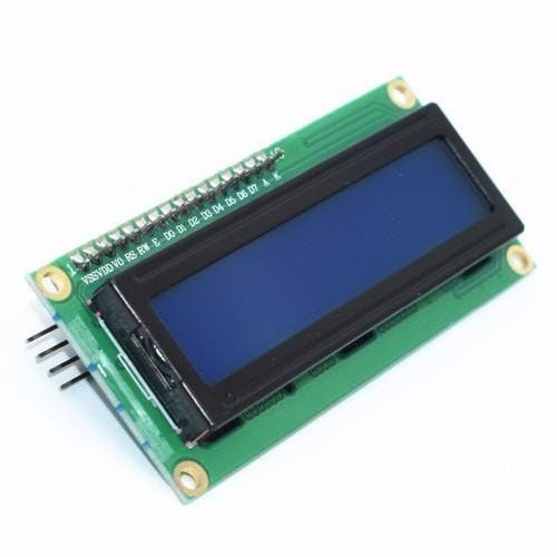
- LCD I2C Display 20X4
- 2x nrf24l01 module
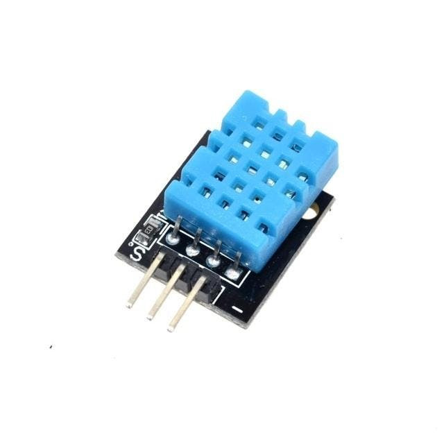
- 2X DHT11 or DHT22 sensor
- Jumper wires
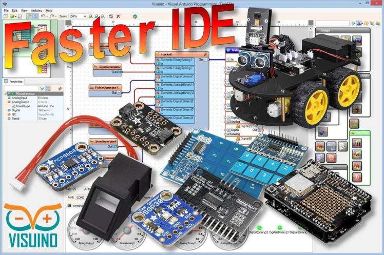
- Visuino program: Download Visuino
1 / 7
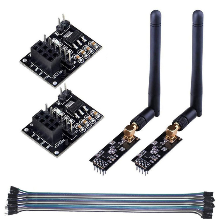

For this project we are using a NRF24L01 module together with a voltage adapter.
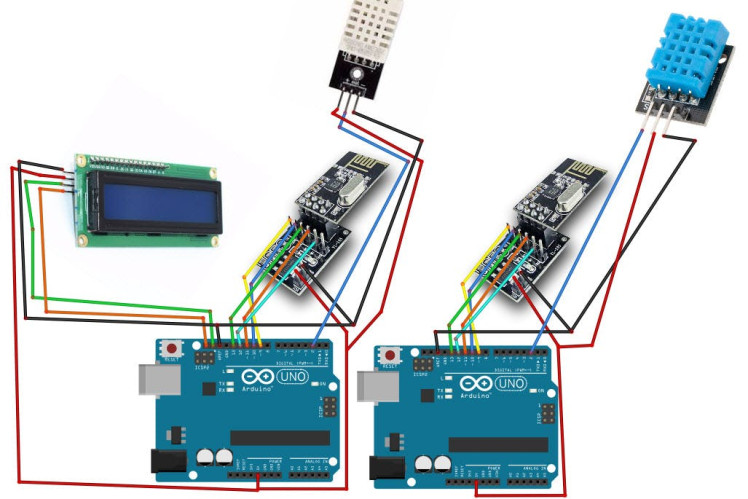
Wiring the Sender Arduino:
- Connect NRF24L01 Adapter pin [VCC] to Arduino pin [5V]
- Connect NRF24L01 Adapter pin [GND] to Arduino pin [GND]
- Connect NRF24L01 Adapter pin "Chip Enable" [CE] to Arduino Digital pin [9]
- Connect NRF24L01 Adapter pin "Chip Select" [CSN] to Arduino Digital pin [10]
- Connect NRF24L01 Adapter pin [SCK] to Arduino Digital pin [13]
- Connect NRF24L01 Adapter pin [MO] to Arduino Digital pin [11]
- Connect NRF24L01 Adapter pin [MI] to Arduino Digital pin [12]
- Connect DHT11 sensor pin [VCC] to Arduino pin [5V]
- Connect DHT11 sensor pin [GND] to Arduino pin [GND]
- Connect DHT11 sensor pin [OUT] to Arduino Digital pin [2]
Wiring the Receiver Arduino:
- Connect NRF24L01 Adapter pin [VCC] to Arduino pin [5V]
- Connect NRF24L01 Adapter pin [GND] to Arduino pin [GND]
- Connect NRF24L01 Adapter pin "Chip Enable" [CE] to Arduino Digital pin [9]
- Connect NRF24L01 Adapter pin "Chip Select" [CSN] to Arduino Digital pin [10]
- Connect NRF24L01 Adapter pin [SCK] to Arduino Digital pin [13]
- Connect NRF24L01 Adapter pin [MO] to Arduino Digital pin [11]
- Connect NRF24L01 Adapter pin [MI] to Arduino Digital pin [12]
- Connect LCD Display pin [SCL] to Arduino pin [SCL]
- Connect LCD Display pin [SDA] to Arduino pin [SDA]
- Connect LCD Display pin [VCC] to Arduino pin [5v]
- Connect LCD Display pin [GND] to Arduino pin [GND]
- Connect DHT12 sensor pin [VCC] to Arduino pin [5V
- Connect DHT12 sensor pin [GND] to Arduino pin [GND]
- Connect DHT12 sensor pin [OUT] to Arduino Digital pin [2]
1 / 2
The Visuino: https://www.visuino.eu also needs to be installed. Download Free version or register for a Free Trial.
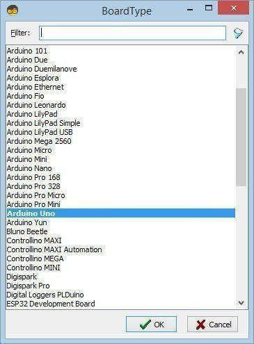
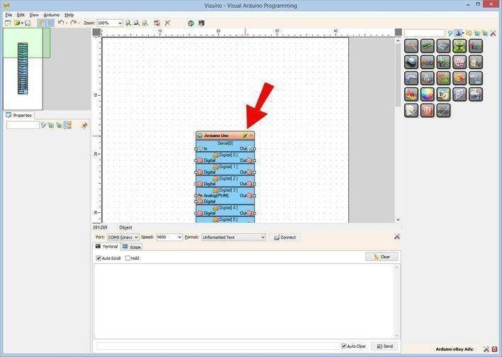
Start Visuino as shown in the first picture Click on the "Tools" button on the Arduino component (Picture 1) in Visuino When the dialog appears, select "Arduino UNO" as shown on Picture 2
Step 4: For Sender Arduino - in Visuino Add, Set & Connect Components1 / 6

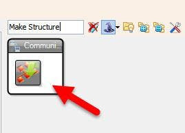

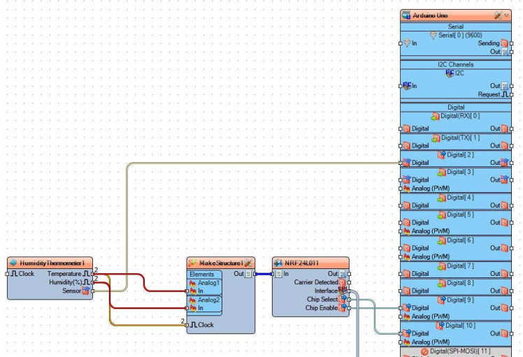
- Add "Make Structure" component
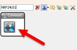
- Add "NRF24L01" component
- Add "DHT" component
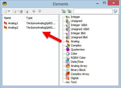
- Double click on the "MakeStructure1" and in the "Elements" window drag 2X "Analog" to the left side and close the "Elements" window
- Close the "Elements" window
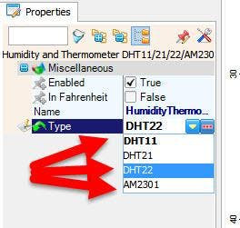
- Select "HumidityThermometer1" and in the properties set "Type" to the sensor that you use, either DHT11, DHT22, etc
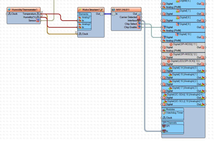
- Connect "HumidityThermometer1" pin [Temperature] to "MakeStructure1" > "Analog1" pin [In]
- Connect "HumidityThermometer1" pin [Humidity] to "MakeStructure1" > "Analog2" pin [In]
- Connect "HumidityThermometer1" pin [Sensor] to Arduino Digital pin [2]
- Connect "NRF24L011" pin Interface [SPI] To Arduino board pin [SPI]
- Connect "NRF24L011" pin [Chip Select] To Arduino board digital pin [10]
- Connect "NRF24L011" pin [Chip Enable] To Arduino board digital pin [9]
- Connect "MakeStructure1" pin [Out] to "NRF24L011" pin [In]
Upload the Project to the Arduino Board (see the Generate, Compile, and Upload the Arduino Code step)
Step 5: For Receiver Arduino - in Visuino Add, Set & Connect Components1 / 20


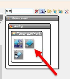
- Add "DHT" component
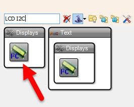
- Add "LCD I2C" component
- Add "NRF24L01" component
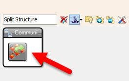
- Add "Split Structure" component
- Select "HumidityThermometer1" and in the properties set "Type" to the sensor that you use, either DHT11, DHT22, etc
- Double click on the "SplitStructure1" and in the "Elements" window drag 2X "Analog" to the left side
- Close the "Elements" window
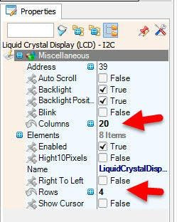
- Select "LiquidCrystalDisplay1" and in the properties window set "Columns" to 20 and "Rows" to 4
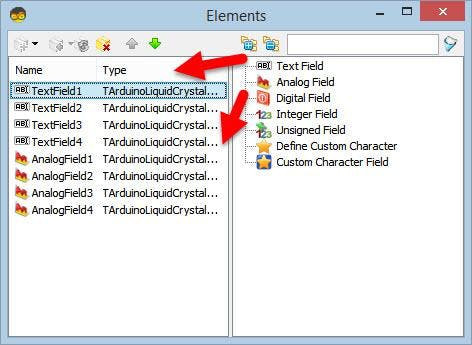
- Double click on the "LiquidCrystalDisplay1" and in the Elements window drag 4X "Text Field" and 4X "Analog Field" to the left side
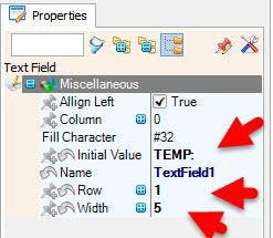
- Select "TextField1" and in the properties window set "Initial Value" to "TEMP:" and "Row" to 1 and "Width" to 5
- Select "TextField2" and in the properties window set "Initial Value" to "HUM::" and "Row" to 3 and "Width" to 5
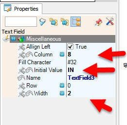
- Select "TextField3" and in the properties window set "Initial Value" to "IN:" and "Column" to 8 and "Width" to 2
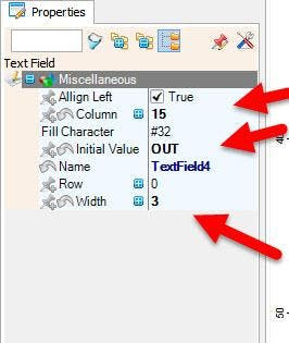
- Select "TextField4" and in the properties window set "Initial Value" to "OUT::" and "Column" to 15 and "Width" to 3
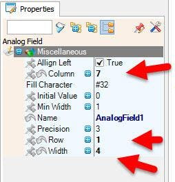
- Select "AnalogField1" and in the properties window set "Column" to 7, "Row" to 1 and "Width" to 4
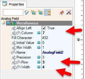
- Select "AnalogField2" and in the properties window set "Column" to 7, "Row" to 3 and "Width" to 4
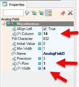
- Select "AnalogField3" and in the properties window set "Column" to 14, "Row" to 1 and "Width" to 4
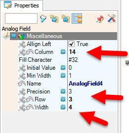
- Select "AnalogField4" and in the properties window set "Column" to 14, "Row" to 3 and "Width" to 4
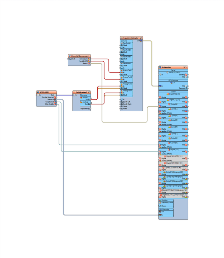
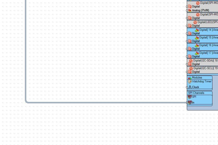
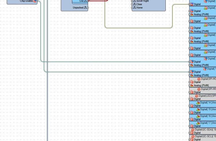
- Connect "NRF24L011" pin Interface [SPI] To Arduino board pin [SPI]
- Connect "NRF24L011" pin [Chip Select] To Arduino board digital pin [10]
- Connect "NRF24L011" pin [Chip Enable] To Arduino board digital pin [9]
- Connect "NRF24L011" pin [Out] to "SplitStructure1" pin [In]
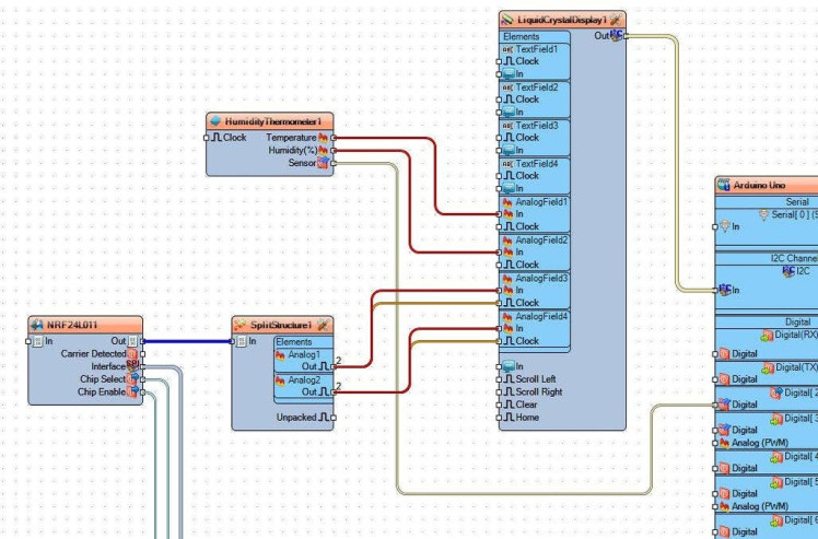
- Connect "HumidityThermometer1" pin [Temperature] to "LiquidCrystalDisplay1" > "AnalogField1" pin [In]
- Connect "HumidityThermometer1" pin [Humidity] to "LiquidCrystalDisplay1" > "AnalogField2" pin [In]
- Connect "HumidityThermometer1" pin [Sensor] to Arduino Digital pin [2]
- Connect "SplitStructure1" > "Analog1" pin [Out] to "LiquidCrystalDisplay1" > "AnalogField3" pin [In] and pin [Clock]
- Connect "SplitStructure1" > "Analog2" pin [Out] to "LiquidCrystalDisplay1" > "AnalogField4" pin [In] and pin [Clock]
- Connect "LiquidCrystalDisplay1" pin I2C [Out] to Arduino pin I2C [In]
Upload the Project to the Arduino Board (see the Generate, Compile, and Upload the Arduino Code step)
Step 6: Generate, Compile, and Upload the Arduino Code
In Visuino, at the bottom click on the "Build" Tab, make sure the correct port is selected, then click on the "Compile/Build and Upload" button.
Step 7: PlayIf you power the Arduino modules, the LCD Display connected to the Receiver Arduino will start to show the Temperature and Humidity inside and Temperature and Humidity from that are received from the sender Arduino.
Congratulations! You have completed your project with Visuino. Also attached are the Visuino project files for Sender and Receiver, that I created for this Tutorial, you can download it and open it in Visuino: https://www.visuino.eu
Schematics, diagrams and documents
Code
Credits
Related products


Leave your feedback...