
Arduino Rc Car Goes North & Adjusts Position Using A Compass

Made by Ron / Drones / Environmental Sensing / Home Automation / Robotics / Sensors
About the project
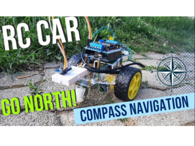
In this Tutorial we will learn how to make a Robot RC car that goes North using a compass.
Project info
Difficulty: Moderate
Estimated time: 1 hour
License: GNU General Public License, version 3 or later (GPL3+)
Items used in this project
Hardware components

Story
When the direction is not North it will adjust its position until it finds North.
This approach is very useful in the environments where GPS is not available or where you need more accurate positioning. Download Project files, Wiring and Full Tutorial here:
If you want do develop the project further one idea could be to add wheel turn counter to measure the distance and perhaps after some distance change direction to South, etc
Have fun exploring this Project!
Also check out this two Tutorials to get more ideas:
Arduino Digital Compass Using MPU9250 Magnetometer
How to Make Arduino Obstacle Avoiding Robot Car With Radar
Step 1: What You Will Need1 / 8
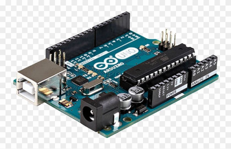


- Arduino UNO (or any other Arduino or ESP)
- MPU9250 (is an accelerometer, gyroscope, magnetometer sensor)
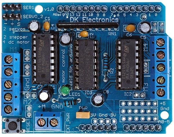
- Adafruit Motor/Stepper/Servo Shield for Arduino kit - v1.2 Learn More about(You can also use other clone Shields that you can buy online) Get it here
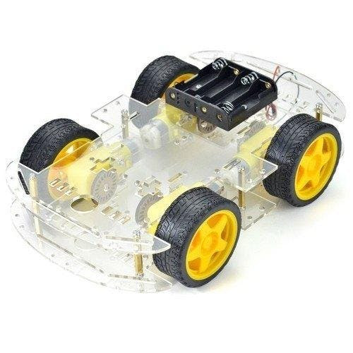
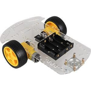
- 2WD or 4WD RC car Chassis Kit
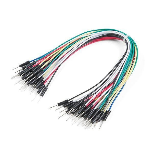
- Jumper wires
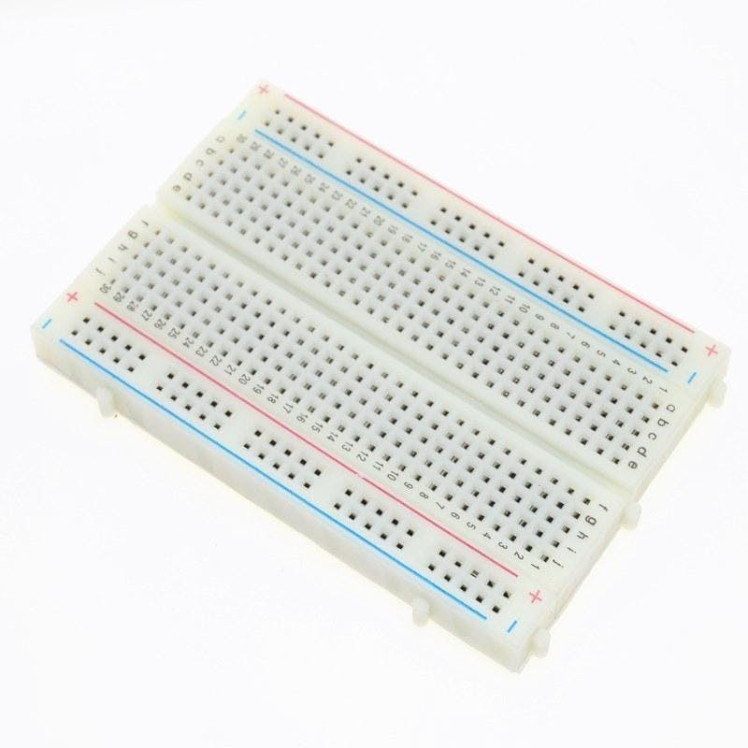
- Breadboard (to attach MPU9250 on)
- Visuino program: Download Visuino
1 / 2
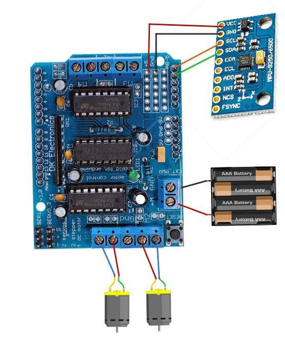
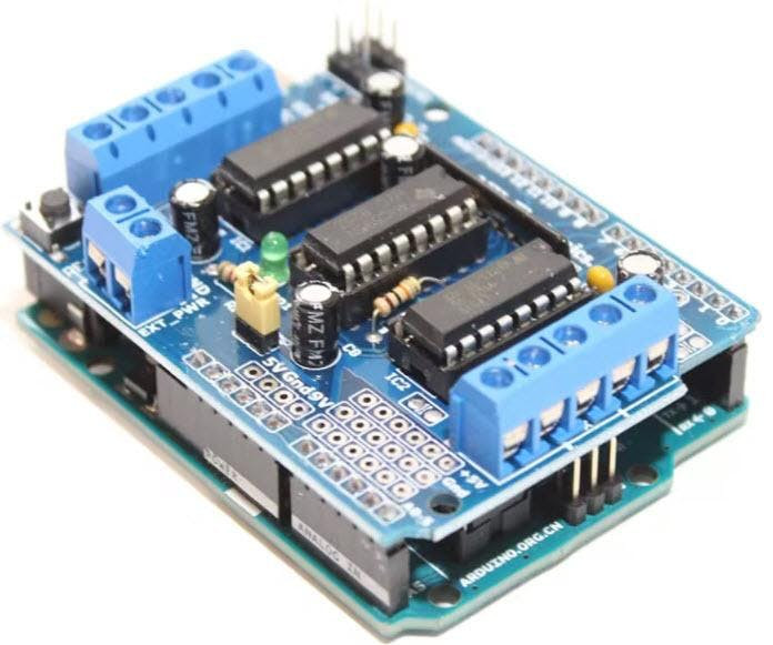
- Attach Motor Shield to the Arduino board
- Connect MPU9250 Sensor pin [SCL] to Motor Shield pin [A5]
- Connect MPU9250 Sensor pin [SDA] to Motor Shield pin [A4]
- Connect MPU9250 Sensor pin [VCC] to Motor Shield pin [5v]
- Connect MPU9250 Sensor pin [GND] to Motor Shield pin [GND]
- Connect DC motor1 wires to the Motor Shield Blue pins [M1]
- Connect DC motor2 wires to the Motor Shield Blue pins [M2]
- Connect Battery red wire (+) to the Motor Shield Blue pin [M+]
- Connect Battery black wire (-) to the Motor Shield Blue pin [GND]
- When you Power the Motor Shield a green LED should be On
1 / 2
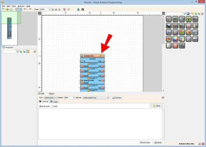
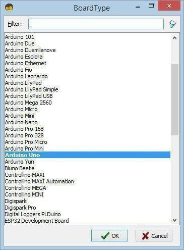
The Visuino: https://www.visuino.eu needs to be installed. Start Visuino as shown in the first picture Click on the "Tools" button on the Arduino component (Picture 1) in Visuino When the dialog appears, select "Arduino UNO" as shown on Picture 2
Step 4: In Visuino Add Components1 / 6


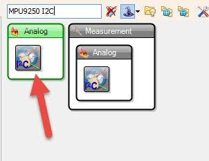
- Add "Accelerometer Gyroscope Compass MPU9250 I2C" component
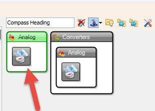
- Add "Compass Heading" component
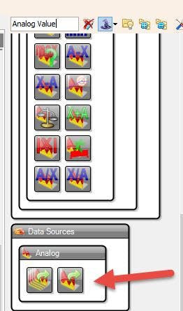
- Add "Compare Analog Range" component
- Add "Analog Value" component
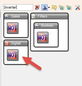
- Add "Digital (Boolean) Inverter (Not)" component
- Add 2X "Speed and Direction To Speed" component
1 / 2
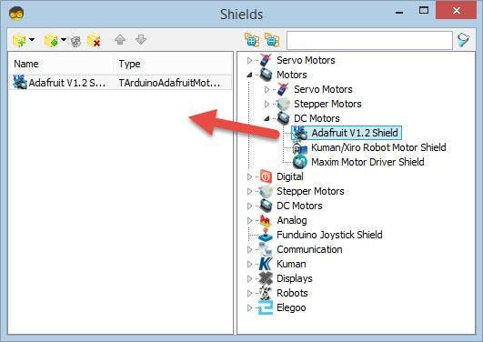
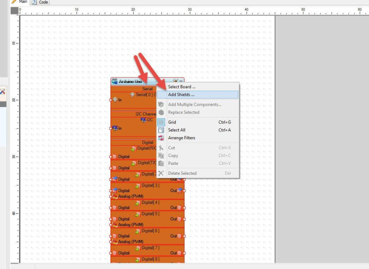
- Right mouse Click on the Arduino board and in the popup menu select "Add Shields" (see Picture1)
- In the "Shields" window select "Adafruit V1.2 Shield" and drag it to the left side (see Picture2)
- Close the "Shields" window
- Select "Analog Value" and in the properties window set "Value" to 0.6 <
- Select "SpeedAndDirectionToSpeed1" and in the Properties window set "Initial Reverse" to True
This will reverse the Start Direction, Depending on your motor wiring, you can leave this to False
- Select "SpeedAndDirectionToSpeed2" and in the Properties window set "Initial Reverse" to True"
This will reverse the Start Direction, Depending on your motor wiring, you can leave this to False
- Select "CompareRange1" and in the Properties window set
- "Range" > "Max" to 350
- "Range" > "Min" to 10
- "Include Limits" to True
1 / 2
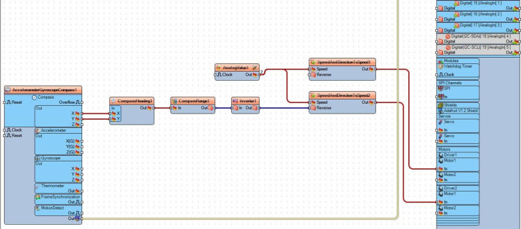
- Connect "AccelerometerGyroscopeCompass1" Compass Pin [X] and Pin [Y] to "CompassHeading1" Pin [X] and Pin [Y]
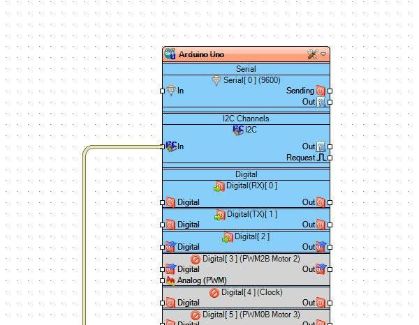
- Connect "AccelerometerGyroscopeCompass1" Pin I2C [Out] to Arduino board pin I2C [In]
- Connect "CompassHeading1" Pin [Out] to "CompareRange1" pin [In]
- Connect "AnalogValue1" pin [Out] to "SpeedAndDirectionToSpeed1" pin [Speed]
- Connect "AnalogValue1" pin [Out] to "SpeedAndDirectionToSpeed2" pin [Speed]
- Connect "CompareRange1" pin [Out] to "Inverter1" pin [In]
- Connect "Inverter1" pin [Out] to "SpeedAndDirectionToSpeed2" pin [Reverse]
- Connect "SpeedAndDirectionToSpeed1" pin [Out] to "Arduino" > "Driver1" pin [Motor1]
- Connect "SpeedAndDirectionToSpeed2" pin [Out] to "Arduino"> "Driver2" pin [Motor1]
- "AccelerometerGyroscopeCompass1" will Give us X & Y values
- "CompassHeading1" will turn X & Y to Degrees that we will use to set the Direction
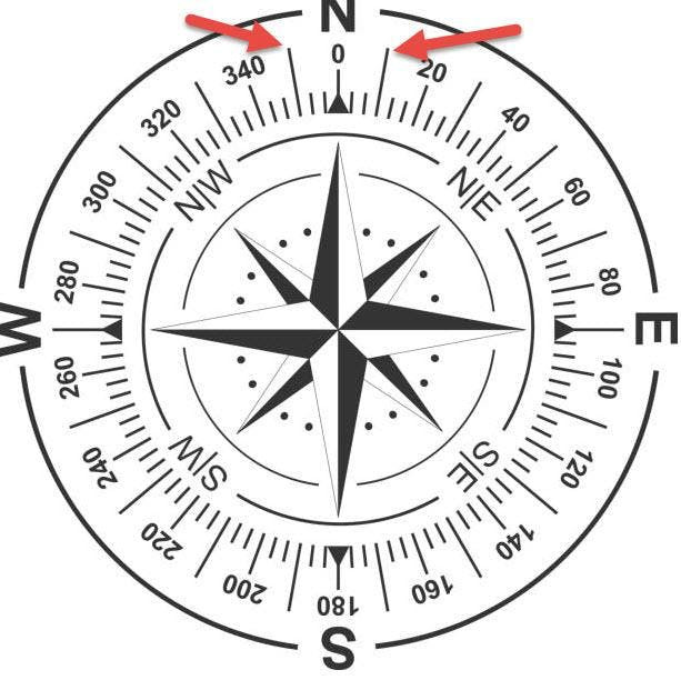
Since the optimal degree would be 0 (See Picture1) we will say if Degrees are Less than 10 or more than 350 we will consider this as being North, everything Else will Trigger The Motor to Reverse.
- "CompareRange1" will determine If it is from 10-350 (Consider not being North) It will trigger the Inverter and then "SpeedAndDirectionToSpeed2" pin [Reverse]
Note: You could lower the range but since the motors are spining quite fast the Compass Sensor might not register the position so fast, this is something to be experimented with.
You can also change the range for other direction if you want, for South you could set "CompareRange1" Max to 190 and Min to 170
Step 9: Generate, Compile, and Upload the Arduino Code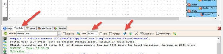
In Visuino, at the bottom click on the "Build" Tab, make sure the correct port is selected, then click on the "Compile/Build and Upload" button.
Step 10: PlayIf you power the Robot car & the Arduino module/Shield, the car wheels will start to spin and if the Direction is not in the "North" range then one wheel will start to reverse it and the car will make circles until it is positioned towards the "North" then it will continue to go straight ahead.
Congratulations! You have completed your project with Visuino. Also attached is the Visuino project, that I created for this Tutorial, you can download it and open it in Visuino: https://www.visuino.eu
Schematics, diagrams and documents
Code
Credits
Related products


Leave your feedback...