
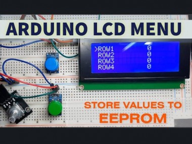
Arduino Lcd Menu With Storing Values To Eeprom

Made by Ron / Communication / Displays / Environmental Sensing / Home Automation / IoT
About the project
In this tutorial we will learn how to make a Menu with buttons and a rotary encoder to set andstore values. Watch the Video!
Items used in this project
Hardware components

Story
In this tutorial we will learn how to make a Menu with buttons and a rotary encoder to set andstore values. Values are then automatically loaded on the start. For this project we are going to use Arduino and the I2C LCD.
Watch the Video!
Step 1: What You Will Need
1 / 5
- LCD Display I2C 20X4 (if you use diferent LCD then make sure that you specify the right Columns and Rows in the Visuino component)
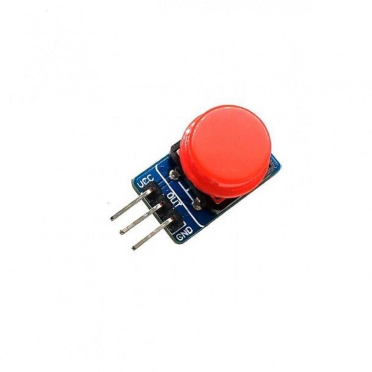
- 2X Button module
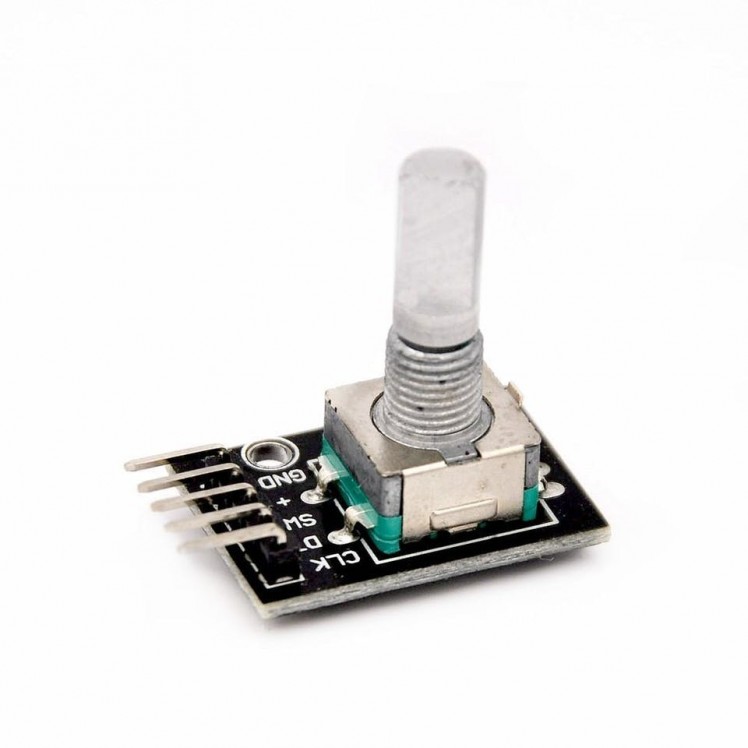
- Rotary Encoder
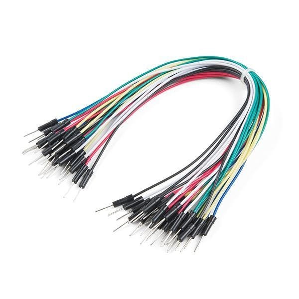
- Jumper wires
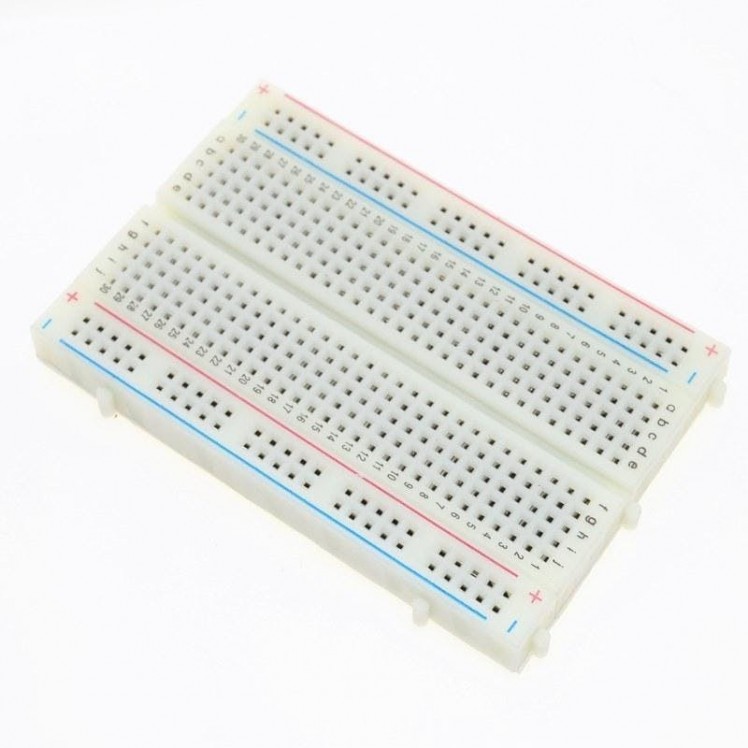
- Breadboard
- Arduino UNO or any other board
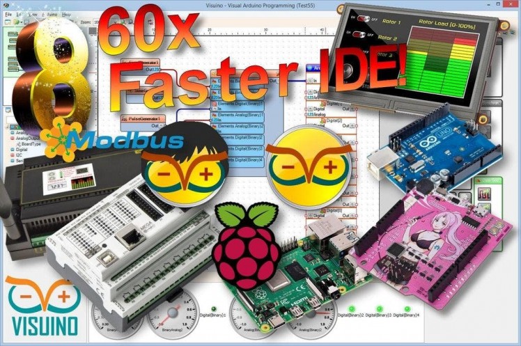
- Visuino software: Download here
Step 2: Circuit
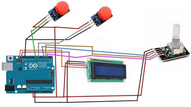
- Connect LCD Display pin VCC to Arduino pin 5V
- Connect LCD Display Module pin GND to Arduino pin GND
- Connect LCD Display pin SCL to Arduino pin SCL
- Connect LCD Display pin SDA to Arduino pin SDA
- Connect Button1 pin VCC to Arduino pin 5V
- Connect Button1 pin GND to Arduino pin GND
- Connect Button1 pin Out to Arduino digital pin 7
- Connect Button2 pin VCC to Arduino pin 5V
- Connect Button2 pin GND to Arduino pin GND
- Connect Button2 pin Out to Arduino digital pin 8
- Connect Rotary Encoder pin Clock [CK] to Arduino digital pin [2]
- Connect Rotary Encoder pin Direction [DT] to Arduino digital pin [3]
- Connect Rotary Encoder pin Switch [SW] to Arduino digital pin [4]
Step 3: Start Visuino, and Select the Arduino UNO Board Type
1 / 2
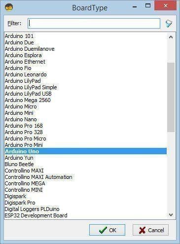
The Visuino: https://www.visuino.eu also needs to be installed. Download Free version or register for a Free Trial.
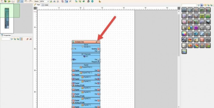
Start Visuino as shown in the first picture Click on the "Tools" button on the Arduino component (Picture 1) in Visuino When the dialog appears, select "Arduino UNO" as shown on Picture 2
Step 4: In Visuino Add Components
1 / 12


- Add 2X "Detect Edge" component
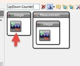
- Add "Up/Down Counter" component
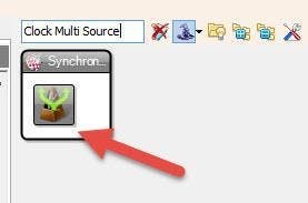
- Add 2X "Clock Multi Source" component
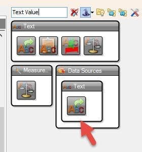
- Add 5X "Text Value" component
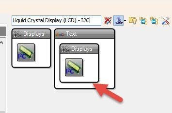
- Add "Liquid Crystal Display (LCD) - I2C" component
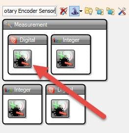
- Add "Rotary Encoder Sensor" component.
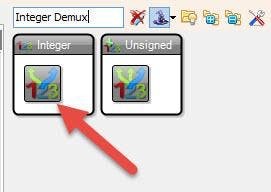
- Add "Integer Demux" component
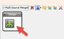
- Add 4x "Integer Multi-Source Merger" component
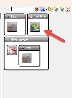
- Add "Start" component.
Step 5: In Visuino Set Components
1 / 20
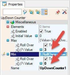

- Select "UpDownCounter1" and in the properties set Max > Value to 3 and Min > Value to 0
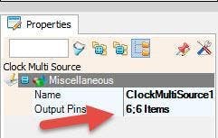
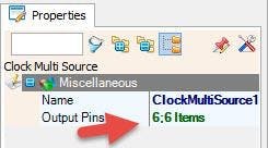
- Select "ClockMultiSource1" and in the properties window set Output Pins to 6
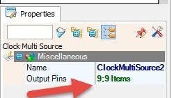
- Select "ClockMultiSource2" and in the properties window set Output Pins to 9
- Select "TextValue1" and in the properties window set Value to ">"
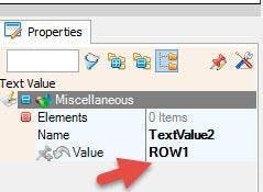
- Select "TextValue2" and in the properties window set Value to "ROW1"
- Select "TextValue3" and in the properties window set Value to "ROW2"
- Select "TextValue4" and in the properties window set Value to "ROW3"
- Select "TextValue5" and in the properties window set Value to "ROW4"
- Select "LiquidCrystalDisplay1" and in the properties window set Columns to 20 and Rows to 4
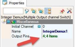
- Select "IntegerDemux1" and in the properties window set Output Pins to 4.
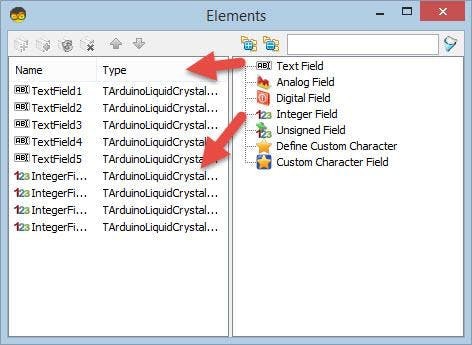
Double click on the "LiquidCrystalDisplay1" and in the Elements window:
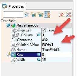
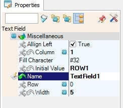
- Drag "Text Field" to the left side and in the properties window set "Column" to 1 and "Initial Value" to "ROW1"
- Drag another "Text Field" to the left side and in the properties window set "Column" to 1 and "Initial Value" to "ROW2" and "Row" to 1
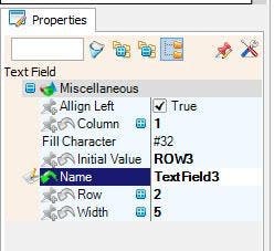
- Drag another "Text Field" to the left side and in the properties window set "Column" to 1 and "Initial Value" to "ROW3" and "Row" to 2
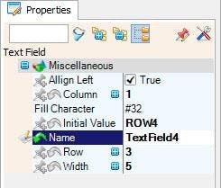
- Drag another "Text Field" to the left side and in the properties window set "Column" to 1 and "Initial Value" to "ROW4" and "Row" to 3
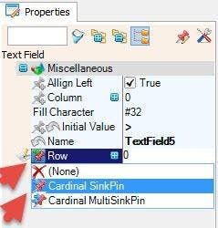
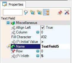
- Drag another "Text Field" to the left side and in the properties window set "Column" to 0 and "Initial Value" to ">" and "Width" to 1, Select "Row" and Click on the pin Icon and select "Cardinal SinkPin"
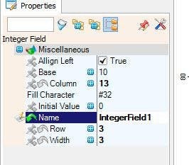
- Drag "Integer Field" to the left, and in the properties window set column to 13 and width to 3
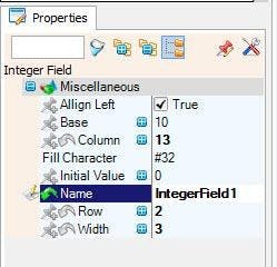
- Drag another "Integer Field" to the left, and in the properties window set column to 13, Row to 1 and width to 3
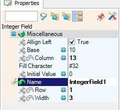
- Drag another "Integer Field" to the left, and in the properties window set column to 13, Row to 2 and width to 3
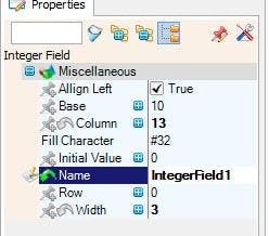
- Drag another "Integer Field" to the left, and in the properties window set column to 13, Row to 3 and width to 3
Close the Elements window
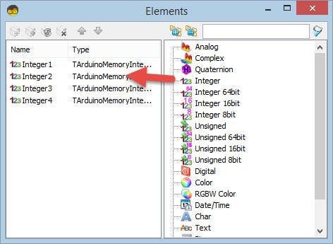
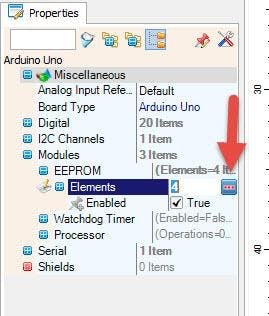
Select Arduino Board and in the properties window expand Modules EEPROM and click on the Elements 3 dots.
- In the Elements window drag 4 Integer Elements to the left side.
Close the Elements window.
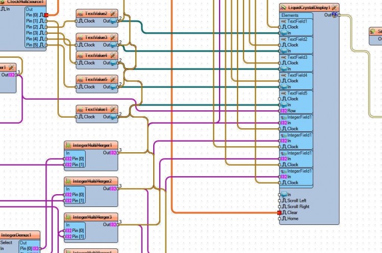
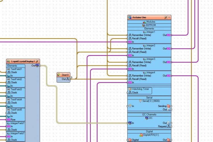
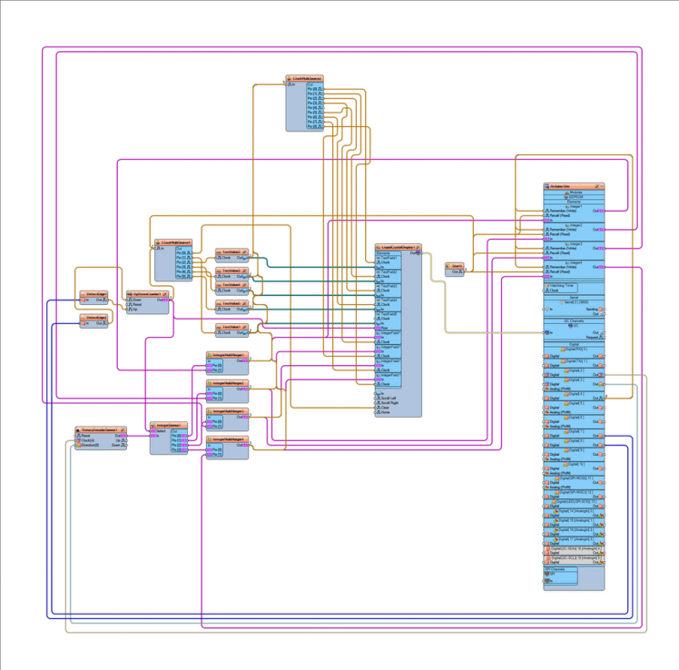
Step 6: In Visuino Connect Components
1 / 3
- Connect Arduino Digital Pin [7] to DetectEdge1 pin [In]
- Connect Arduino Digital Pin [8] to DetectEdge2 pin [In]
- Connect DetectEdge1 pin [Out] to UpDownCounter1 pin [Up]
- Connect DetectEdge2 pin [Out] to UpDownCounter1 pin [Down]
- Connect UpDownCounter1 pin [Out] to LiquidCrystalDisplay1 > Text Field5 pin [Row]
- Connect UpDownCounter1 pin [Out] to ClockMultiSource1 pin [In]
- Connect ClockMultiSource1 pin [0] to LiquidCrystalDisplay1 pin [Clear]
- Connect ClockMultiSource1 pin [1] to TextValue1 pin [Clock]
- Connect ClockMultiSource1 pin [2] to TextValue2 pin [Clock]
- Connect ClockMultiSource1 pin [3] to TextValue3 pin [Clock]
- Connect ClockMultiSource1 pin [4] to TextValue4 pin [Clock]
- Connect ClockMultiSource1 pin [5] to TextValue5 pin [Clock]
- Connect TextValue2 pin [Out] to LiquidCrystalDisplay1 > Text Field1 pin [In]
- Connect TextValue3 pin [Out] to LiquidCrystalDisplay1 > Text Field2 pin [In]
- Connect TextValue4 pin [Out] to LiquidCrystalDisplay1 > Text Field3 pin [In]
- Connect TextValue5 pin [Out] to LiquidCrystalDisplay1 > Text Field4 pin [In]
- Connect "LiquidCrystalDisplay1" pin I2C [Out] to Arduino pin I2C [In]
- Connect Arduino Digital pin [2] to "RotaryEncoderSensor1" pin [Clock]
- Connect Arduino Digital pin [3] to "RotaryEncoderSensor1" pin [Direction]
- Connect Arduino Digital pin [4] to Arduino Integer1 pin [Remember], Integer2 pin [Remember], Integer3 pin [Remember] and Integer4 pin [Remember]
- Connect "Start1" pin [Out] to Arduino Integer1 pin [Recall], Integer2 pin [Recall], Integer3 pin [Recall] and Integer4 pin [Recall] and "ClockMultiSource1" pin [In]
- Connect "UpDownCounter1" pin [Out] to "IntegerDemux1" pin [Select]
- Connect "RotaryEncoderSensor1" pin [Out] to "IntegerDemux1" pin [In]
- Connect "IntegerDemux1" Out pin [0], pin[1],pin[2],pin[3] to "IntegerMultiMerger1","IntegerMultiMerger2","IntegerMultiMerger3","IntegerMultiMerger4" pin [0]
- Connect Arduino Integer1 pin [Out] to "IntegerMultiMerger1" pin [1]
- Connect Arduino Integer2 pin [Out] to "IntegerMultiMerger2" pin [1]
- Connect Arduino Integer3 pin [Out] to "IntegerMultiMerger3" pin [1]
- Connect Arduino Integer4 pin [Out] to "IntegerMultiMerger4" pin [1]
- Connect "IntegerMultiMerger1" pin [Out] to "LiquidCrystalDisplay1" > "IntegerField1" pin [In] and Arduino Integer1 pin [In]
- Connect "IntegerMultiMerger2" pin [Out] to "LiquidCrystalDisplay1" > "IntegerField2" pin [In] and Arduino Integer2 pin [In]
- Connect "IntegerMultiMerger3" pin [Out] to "LiquidCrystalDisplay1" > "IntegerField3" pin [In] and Arduino Integer3 pin [In]
- Connect "IntegerMultiMerger4" pin [Out] to "LiquidCrystalDisplay1" > "IntegerField4" pin [In] and Arduino Integer4 pin [In]
- Connect "TextValue2" pin [Out] to "ClockMultiSource2" pin [In]
- Connect "TextValue3" pin [Out] to "ClockMultiSource2" pin [In]
- Connect "TextValue4" pin [Out] to "ClockMultiSource2" pin [In]
- Connect "TextValue5" pin [Out] to "ClockMultiSource2" pin [In]
- Connect "TextValue1" pin [Out] to "ClockMultiSource2" pin [In]
- Connect "IntegerMultiMerger1" pin [Out] to "ClockMultiSource2" pin [In]
- Connect "IntegerMultiMerger2" pin [Out] to "ClockMultiSource2" pin [In]
- Connect "IntegerMultiMerger3" pin [Out] to "ClockMultiSource2" pin [In]
- Connect "IntegerMultiMerger4" pin [Out] to "ClockMultiSource2" pin [In]
- Connect "ClockMultiSource2" pin [Out] [0] to "LiquidCrystalDisplay1" "TextField1" pin [Clock]
- Connect "ClockMultiSource2" pin [Out] [1] to "LiquidCrystalDisplay1" "TextField2" pin [Clock]
- Connect "ClockMultiSource2" pin [Out] [2] to "LiquidCrystalDisplay1" "TextField3" pin [Clock]
- Connect "ClockMultiSource2" pin [Out] [3] to "LiquidCrystalDisplay1" "TextField4" pin [Clock]
- Connect "ClockMultiSource2" pin [Out] [4] to "LiquidCrystalDisplay1" "TextField5" pin [Clock]
- Connect "ClockMultiSource2" pin [Out] [5] to "LiquidCrystalDisplay1" "IntegerField1" pin [Clock]
- Connect "ClockMultiSource2" pin [Out] [6] to "LiquidCrystalDisplay1" "IntegerField2" pin [Clock]
- Connect "ClockMultiSource2" pin [Out] [7] to "LiquidCrystalDisplay1" "IntegerField3" pin [Clock]
- Connect "ClockMultiSource2" pin [Out] [8] to "LiquidCrystalDisplay1" "IntegerField4" pin [Clock]
Step 7: Generate, Compile, and Upload the Code
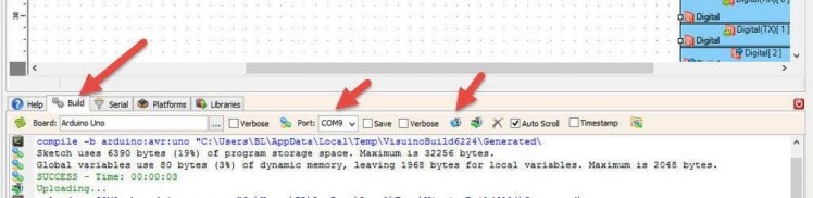
In Visuino, at the bottom click on the "Build" Tab, make sure the correct port is selected, then click on the "Compile/Build and Upload" button.
Step 8: Play
If you power the Arduino module and by pressing the buttons you will be able to change the menu selection on the LCD and change the values using a rotary encoder. If you press the button on the rotary encoder the values will be stored to Arduino EEPROM and loaded on the start.
Congratulations! You have completed your project with Visuino. Also attached is the Visuino project, that I created for this tutorial, you can download it and open it in Visuino: https://www.visuino.eu
Schematics, diagrams and documents
Code
Credits
Related products


Leave your feedback...