
Arduino Acs712 Current Sensor Using Visual Programming

Made by Ron / Displays / Environmental Sensing / Home Automation / Notifications / Sensors
About the project
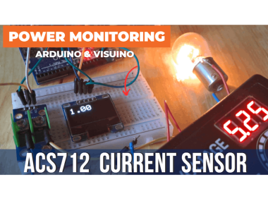
How to use the ACS712 Current Sensor with Visuino and Arduino to measure both AC & DC currents and show the values in Amps on the display.
Items used in this project
Hardware components

Story
In this tutorial, we'll explore how to use the ACS712 Current Sensor with Visuino and Arduino to measure both AC and DC currents and display the readings in Amps on an OLED screen. The ACS712 is a Hall-effect-based sensor that provides accurate current measurements, making it ideal for various applications such as motor control and power monitoring.
Watch the video!
Step 1: What You Will Need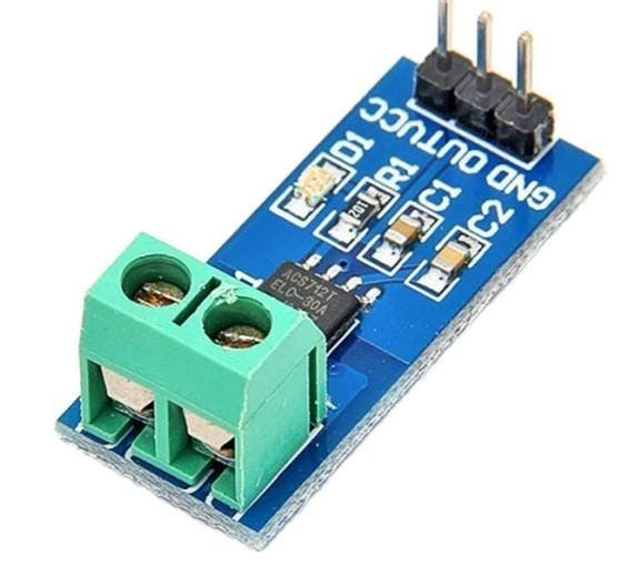

- ACS712 s ensor
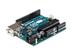
- Arduino board (or any other board)
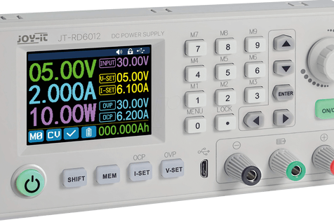
- Power Supply
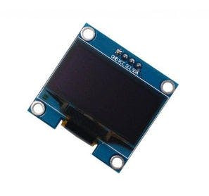
- OLED Display
- Breadboard
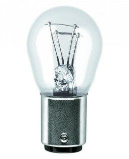
- Some load like a light bulb or DC motor
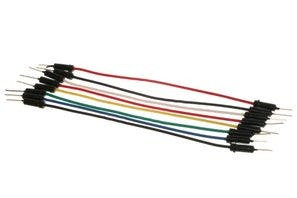
- Jumper wires
- Visuino program: Download Visuino
Understanding the ACS712 Sensor
The ACS712 sensor comes in three variants, each designed for different current ranges:
- ACS712-05B: ±5A with a sensitivity of 185 mV/A
- ACS712-20A: ±20A with a sensitivity of 100 mV/A
- ACS712-30A: ±30A with a sensitivity of 66 mV/A
Choose the appropriate sensor based on the expected current in your application.
Step 2: The Circuit
- Connect OLED Display pin [SCL] to Arduino pin [SCL]
- Connect OLED Display pin [SDA] to Arduino pin [SDA]
- Connect OLED Display pin [VCC] to Arduino pin [5v]
- Connect OLED Display pin [GND] to Arduino pin [GND]
- Connect ACS712 pin[VCC] to the [5V] pin on the Arduino.
- Connect ACS712 pin[GND] to the [GND] pin on the Arduino.
- Connect ACS712 pin [Out]to the [A0] analog input pin on the Arduino.
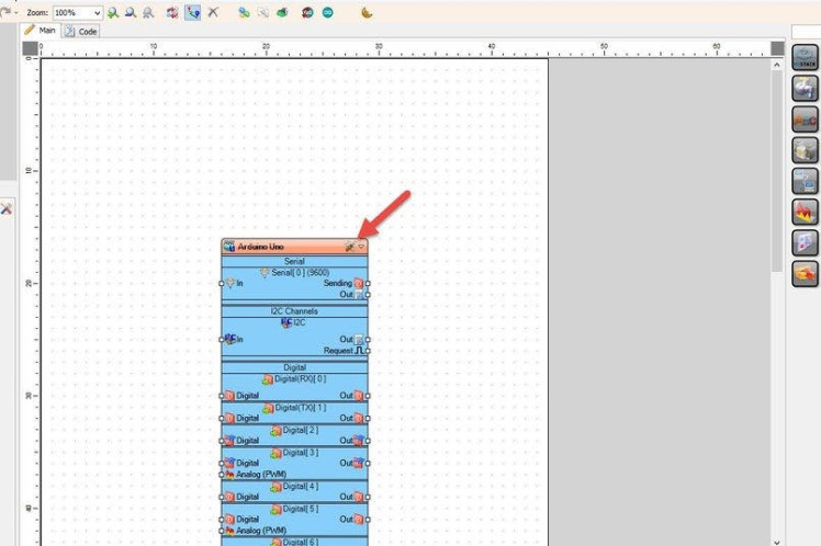
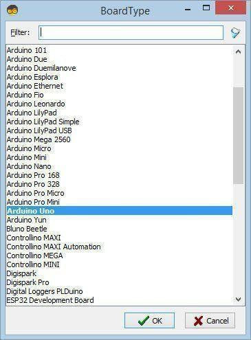
Start Visuino as shown in the first picture Click on the "Tools" button on the Arduino component (Picture 1) in Visuino When the dialog appears, select "Arduino UNO" as shown on Picture 2
Step 4: In Visuino Add, Set & Connect Components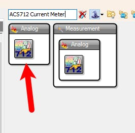


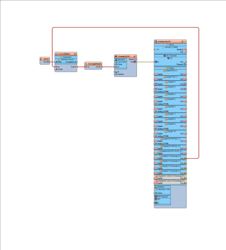
- Add "ACS712 Current Meter" component
- Add "OLED I2C" component
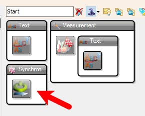
- Add "Start" component
- Add "Average Analog Period" component
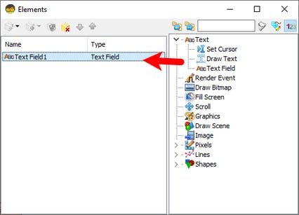
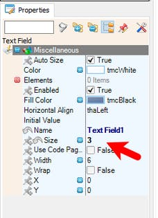
- Double click on the "DisplayOLED1" component and in the Elements window drag "Text Field" to the left side and in the properties window set "Size" to 3
- Close the Elements window
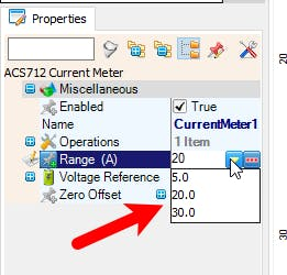
- Select "CurrentMeter1" and in the properties window set the type of your sensor by selecting "Range (A)" in this example we are using 20 (ACS712-20A)
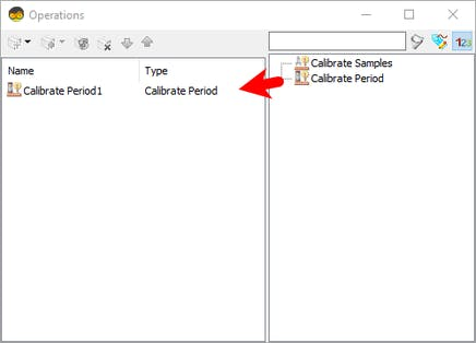
- Double click on the "CurrentMeter1" and in the Operations window drag "Calibrate Period" to the left side and in the properties window set "Period (uS)" to 3000000, This means that on the start the sensor will calibrate it self for 3s
- Close the Operations window
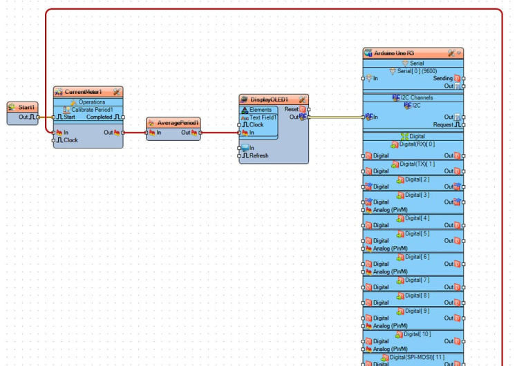
- Connect Arduino Analog 0 pin [Out] to "CurrentMeter1" pin [In]
- Connect "Start1" pin [Out] to "CurrentMeter1" > "Calibrate Period1" pin [Start]
- Connect "CurrentMeter1" pin [Out] to "AveragePeriod1" pin [In]
- Connect "AveragePeriod1" pin [Out] to "DisplayOLED1" > "Text Field1" pin [In]
- Connect "DisplayOLED1" pin [I2C] to Arduino pin [I2C]

In Visuino, at the bottom click on the "Build" Tab, make sure the correct port is selected, then click on the "Compile/Build and Upload" button.
Step 6: PlayCongratulations! You have completed your project with Visuino. Also attached is the Visuino project, that I created for this Instructable, you can download it and open it in Visuino: https://www.visuino.com
Schematics, diagrams and documents
Code
Credits
Related products


Leave your feedback...