
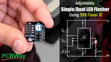
Adjustable Single/dual Led Flasher Using 555 Timer Ic

Made by tarantula3 / Displays / Home Automation / Lights / Robotics / Sensors
About the project
In this tutorial, I'll first blink "an LED" using the positive pulse generated by a "DIY 555 Pulse Generator Module", followed by "two LEDs" alternating and flashing at a regular interval.
Project info
Difficulty: Easy
Platforms: Adafruit, Arduino, NodeMCU, MicroPython, PCBWay
Estimated time: 1 hour
License: GNU Lesser General Public License version 3 or later (LGPL3+)
Items used in this project
Hardware components

Story
In this tutorial, I'll first blink "an LED" using the positive pulse generated by a "DIY 555 Pulse Generator Module" (video: https://youtu.be/bMAnipPOjFo), followed by "two LEDs" alternating and flashing at a regular interval. The output frequency of pulses can be adjusted using a potentiometer. The circuit can be operated from any voltage between 5 to 15 volt DC.
Watch this video for detailed step by step instructions on how to build this circuit and for a complete instruction on how the circuit works.
Items Required

2 x LEDs
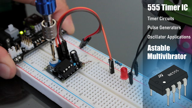
1 x 555 Timer IC
1 x 10µF Capacitor
1 x 220Ω Resistor
1 x 1kΩ Resistor
1 x 10kΩ Resistor and/or
1 x 10kΩ Potentiometer
Circuit Diagram

How The Circuit Works


* Capacitor C1 will be in a discharged state immediately when we firing up the circuit. * So, the voltage at Pin 2 will be 0v which is less than 1/3rds of the supply voltage, this will turn ON the output on Pin 3.* At the same time Pin 7 will internally disconnect from the GND and the Capacitor C1 will start changing via resistors R1 and R2.* Once the voltage across capacitor C1 crosses 2/3rds of the supply voltage, Pin 6 turns OFF the output.* At the same time Pin 7 will internally reconnect to the GND causing the capacitor C1 to discharge via resistor R1.
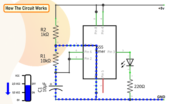
* Once the voltage across the capacitor C1 falls below 1/3rd of the supply voltage, Pin 2 turns ON the output, and the above cycle keeps repeating itself.You can hook up a multimeter to the circuit to measure the charging and discharging of the capacitor.
Since resistance R1 is involved in both charging and discharging of the Capacitor, increasing or decreasing its value will increase or decrease the duration of the OFF cycle and will decrease or increase the flashing rate of the LED, as the capacitor will take more time to charge and discharge.By replacing the capacitor with a higher or lower value, you can also get a longer or shorter flashing rate.By replacing the resistor R1 with a potentiometer the blinking rate of the LED can be dynamically adjusted.
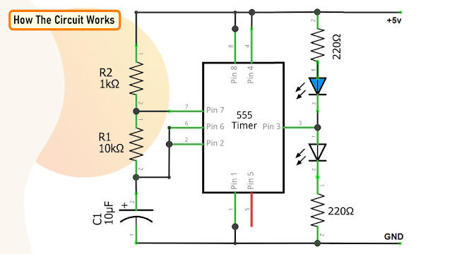
Now, for the Dual LED flashing effect we need to connect a second LED with opposite polarity to the Pin 3 of the IC. That's it, as easy as that.
Calculations

There are many online calculators to calculate this online. I will provide a link to one of the astable calculators in the description below: https://ohmslawcalculator.com/555-astable-calculator
Lets first calculate the value of t1 or the 'capacitor charge “ON” time which is 0.693(R1 + R2 ) * C1. Putting the values together we get 76.23 milliseconds. Now, for capacitor discharge “OFF” time or t2 we need to multiply 0.693 to R2 and C1, which then gives us a value of 69.3 milliseconds.
Next, the total periodic time T is equal to t1 + t2 which comes out to be 145.53 milliseconds.
The output frequency, ƒ is therefore comes out to be to 6.871Hz.Which gives a duty cycle value of 52.38% If you want to have more control over the charging and discharging use a higher value for R2 (100K) and lower value for R1 (1K). That way you will have 99% control over the charging and discharging resistance in the circuit.
The maximum output current of this IC is 200mA therefore to drive a higher current load of up to 1A we have to use a transistor like the BD135.
The Board

So, this is how my board looks like in 2D and 3D. There are 16 breakout boards in this 100cm x 100cm assembly. You can download the gerber file from the link provided in the description below and order it from PCBWay.
Soldering

Then let's solder the potentiometer to the board. After that lets solder the 1kΩ (R1) resistor to the board followed by the 10µF capacitor (C1) to the board. Once done, let's insert the 555 timer IC to the IC base.To conclude I have soldered 3 x Male pin headers to the board.
Applications and Uses
- This circuit can be used to control the speed of DC motors and Stepper motors
- It can be used to control windscreen wiper motors to generate a to-and-fro motion
- It can be used as square wave signal generator
- It can be used as an adjustable pulse generator for MCUs
- In Strobe lights and SoS signaling circuits
- Telecommunications for encoding purposes
- In turning indicator circuits for all types of vehicles and bicycles
- To generate adjustable pulse (timing pulses) to control other circuits. As, in combination with the 4017 & 4026 ICs

- I have used this IC in few of my other projects and tutorials like the:
- DIY - Boba Fett Helmet With LED Chaser Circuit : https://youtu.be/vtO_GD0SS2s
- LED Chaser Circuits Using IC4017 and Arduino : https://youtu.be/F6V1AjESWbU
- DIY - LAN CABLE TESTER : https://youtu.be/PSK5Aa-byHA
- 555 Pulse Generator Module : https://youtu.be/bMAnipPOjFo
Thanks
Full Blog Post: Blog Post
Video: Video Link
Related Videos
1. DIY - Boba Fett Helmet With LED Chaser Circuit : Video Link
2. LED Chaser Circuits Using IC4017 and Arduino : Video Link
3. DIY - LAN CABLE TESTER : Video Link
4. 555 Pulse Generator Module, How it Works : Video Link
Gerber File: Download
Calculator: Download
Schema: Download
Support My Work
BTC: 1M1PdxVxSTPLoMK91XnvEPksVuAa4J4dDp
LTC: MQFkVkWimYngMwp5SMuSbMP4ADStjysstm
DOGE: DDe7Fws24zf7acZevoT8uERnmisiHwR5st
ETH: 0x939aa4e13ecb4b46663c8017986abc0d204cde60
BAT: 0x939aa4e13ecb4b46663c8017986abc0d204cde60
LBC: bZ8ANEJFsd2MNFfpoxBhtFNPboh7PmD7M2
Thanks, ca again in my next tutorial.
Schematics, diagrams and documents
Credits
Related products


Leave your feedback...