
Using Inkscape to design and create projects ready for the K40 [Part 2]
In this part of the K40 laser cutter series we shall learn how to create graphics ready for cutting on the K40 using a free vector image editor and when it comes to editing vector images, the industry standard is Adobe Illustrator, but that comes at a great cost. So, an alternative was created and it was called Inkscape. Inkscape is a fantastic vector image editing tool, it provides (nearly) the same features as Illustrator, but with zero cost! So, let’s learn more about Inkscape and how we can use it to create projects ready to be created in our K40 laser cutter.
Installing Inkscape
Inkscape is available for Windows, Mac and Linux machines and it can be downloaded via inkscape.org or your operating systems package manager. Windows users can also download a portable version from PortableApps.com (https://portableapps.com/apps/graphics_pictures/inkscape_portable)
With Inkscape installed, open the application and take a look at the user interface. In the centre of the screen is an A4 page, rotated to portrait. On the left of the screen are a series of tools that enable us to create shapes (squares, circles, geometric shapes etc.), edit text and edit the properties of objects. To the bottom of the screen is a colour palette, this is used to alter the colours of the objects, their fill and line colour (stroke). The colour of the stroke that our shape has will denote how it is managed by the laser cutter.
Setting up the document to match the K40
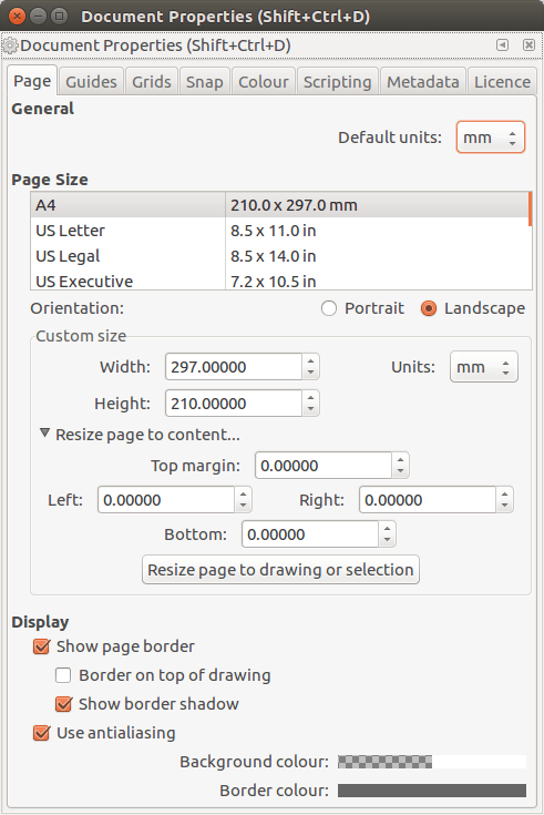
The K40 laser cutter has a cutting area that is roughly A4 sized, but rather than the default portrait orientation used by Inkscape, it is in landscape, so we need to edit the preferences of Inkscape so that they match the K40. From the File menu, select Document Properties then set up your page as follows.
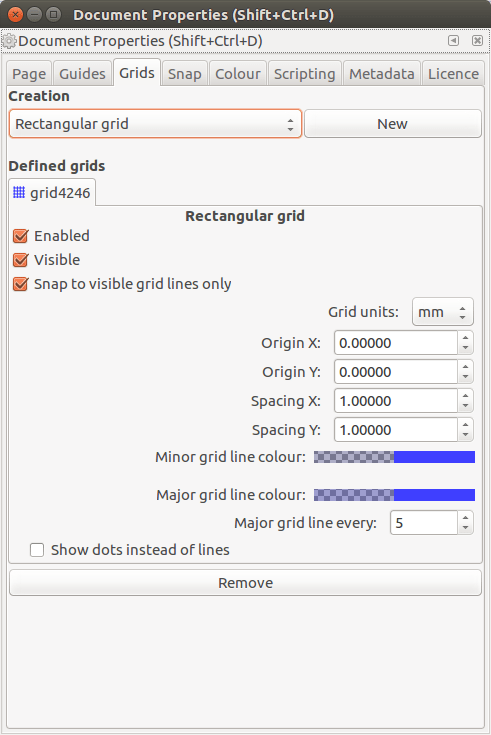
Still in the Document Properties window, go to the Grids tab and create a new grid using the following options..
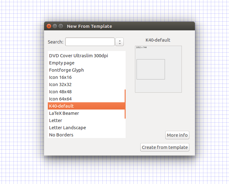
Once these configuration steps are made, our document will be ready for use with the K40. You will need to repeat these steps each time unless you save your document as K40 Default in your Templates directory. For Windows it is C:\Program Files\Inkscape\share\templates; for Linux it is located in /usr/share/inkscape/templates/ (Linux users will need to copy their K40 Default file using the sudo prefix as the templates directory is owned by root. Templates can then be found under the File menu inside Inkscape.
So now let's start using Inkscape!
Creating shapes
We’ll start by creating a square/rectangle shape in the centre of the page. This can be any size – it is just to get used to using the tool. Left click and hold, then drag the shape into life.
This shape has a stroke (line) colour of black, and it has no fill. We can change the stroke and fill colour quite easily by dragging a block of the chosen colour and placing it over the Fill, Stroke options in the bottom left of the screen. Choosing the correct colours will be vital in the third part of this series as the software used to control the K40 relies on specific stroke colours to denote how the K40 act.
Black: A raster engrave, similar to how an inkjet printer sprays dots across a page, left to right, top to bottom. (About 100mm per second, but can be increased to 180mm.)
Blue: A vector engrave, the laser unit traces the shapes drawn in the document to create fluid lines. (About 20mm per second, best to keep it at this speed.)
Red: A vector cut, a slower sequence that relies on power and speed to ensure a clean cut. (About 10mm per second, best to keep it at this speed.)
Objects can be resized and rotated. To resize just drag the arrows at each point of the object. To rotate, single left-click on the object to change the arrows into rotation arrows.
Objects such as rectangles can also be edited to create rounded corners. All we need to do is to click on the Rectangle Tool and then single left-click on the object. You will see a series of white “dots” appear, use these to drag until the corners are rounded as desired.
Play around with the different objects and get a feel for how they can be used.
Creating complex shapes
If we need to create more complex shapes, for example, shapes that require merging multiple objects, then we can merge objects to create one single object. This is called “union” and it can be found in the Path menu. In this example, we have three circles and a rectangle, which we shall merge into one shape. Select all the shapes, then click on Path >> Union to merge them.
As well as adding shapes together to make one complex shape, we can cut sections of shapes away. This is called “difference” and it too can be found in the Path menu. Use it just like the Union tool, but the top most object is cut out of the shape. Here we can see a “star” shape being cut out of the object.
Have a play with various objects and see what you can make!
Using Guides
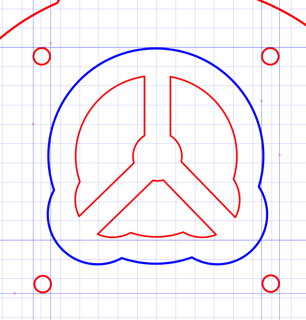
Guides are really useful but criminally underused! A guide is a line that is used as a reference point, a marker, etc., to ensure that your objects are aligned and measured correctly. Here we can see a series of guides that will be used in the next part of this series. These guides are used to ensure that the screw holes for my speaker are aligned correctly.
To create Guides, all we need to do is left click and drag from the measuring line (top and left of the page) and then drop them where needed.
Measuring distances and being precise!
Laser cutting is about precision. If you are precise in your measurements, then you can’t go far wrong. Using the guides created for the project as markers, we can use the Measurement tool to measure between the guides. This will return the values in the default units selected in the Document Properties menu, which we earlier set to mm. Left click and drag between the two guides to measure the distance.
It is also worth pointing out that when cutting screw holes, it is best to go slightly bigger than the actual diameter of the screw thread. For example the screw holes around the perimeter of the project are 3mm in diameter, to match the screw, but when cut they were slightly smaller, around 2.98mm. So you can either force a screw thread through or make the holes slightly larger than needed, around 0.1 - 0.3mm extra diameter.
Tracing Bitmap Images
Inkscape is a vector image editor, and this means that documents can be scaled with no loss of quality. But try and scale a 128px x 128px bitmap image to A1 size and you will see lots of pixels! So we can import a bitmap image File >> Import and then we can click on Path >> Trace Bitmap then it is a matter of trial and error. In the mode tab try out Brightness cutoff and Edge Detection, click on Preview to see how the image will look. Once happy click on Ok to trace the image.
Tracing can also be used for tracing bitmap images used as reference material for projects, handy when needing a 1:1 sized reference image.
Conclusion
So, there we have it, enough skills and knowledge to use Inkscape to take our first step into Laser cutting. In the next and final part of the series we shall create a project using Inkscape and then cut the pieces on the K40 laser cutter ready for assembly into a final product!

Les Pounder loves hacking and tinkering with Arduino, Raspberry Pi and new technologies. He passes on his skills and discoveries to Electromaker readers via tutorials and reviews.


Leave your feedback...