
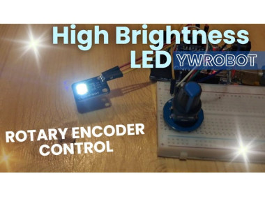
Ywrobot High Brightness Led Control With Rotary Encoder

Made by Ron / Home Automation / Lights / Security / Sensors
About the project
In this Visual Programming (Visuino) tutorial, we’ll use the YwRobot High Brightness Lighting LED Module and a Rotary Encoder to control LED
Project info
Difficulty: Easy
Platforms: Arduino, DFRobot, Visuino
Estimated time: 1 hour
License: GNU General Public License, version 3 or later (GPL3+)
Items used in this project
Hardware components

Software apps and online services
Story
In this Visual Programming (Visuino) tutorial, we’ll use the YwRobot High Brightness Lighting LED Module and a Rotary Encoder to control LED brightness and blinking modes.
- Rotate the encoder to smoothly adjust LED brightness from low to high (and vice versa).
- Press the encoder button to toggle between steady glow and blinking mode.
- Brightness can be adjusted in both modes for complete flexibility.
This project shows how simple it is to build interactive lighting effects with Arduino and Visual Programming (Visuino).
Note: you can use any other LED, it will work the same.
Watch the Video!
Step 1: What You Will Need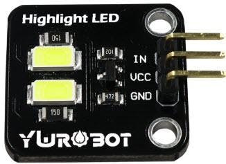
- YwRobot High Brightness Lighting LED Module
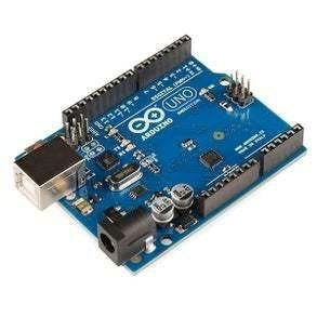
- Arduino (or any other board)
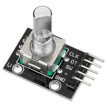
- Rotary Encoder module
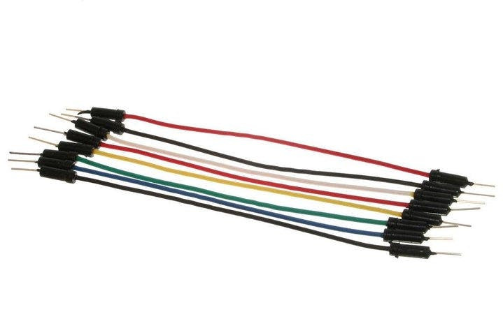
- Jumper wires
- Visuino program: Download Visuino
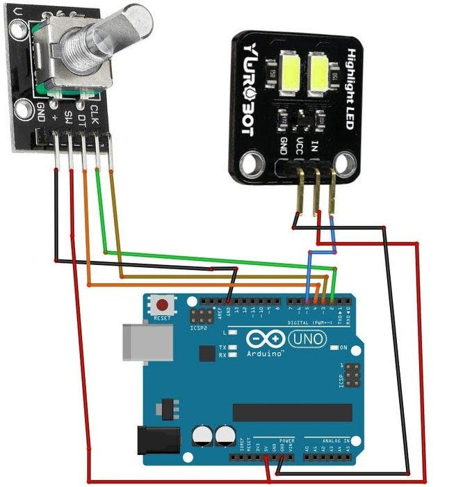
Rotary Encoder Module Connections
- Connect Encoder pin [CLK] to Arduino pin [2]
- Connect Encoder pin [DT] to Arduino pin [3]
- Connect Encoder pin [SW] to Arduino pin [4]
- Connect Encoder pin [+ (VCC)] to Arduino pin [5V]
- Connect Encoder pin [GND] to Arduino pin [GND]
- Connect LED module pin [+ (VCC)] to Arduino pin [5V]
- Connect LED module pin [GND] to Arduino pin [GND]
- Connect LED module pin [IN] to Arduino digital PWM pin [5]
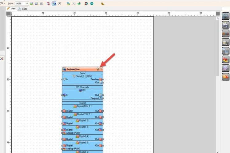
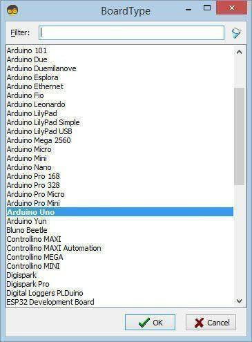
Start Visuino as shown in the first picture Click on the "Tools" button on the Arduino component (Picture 1) in Visuino When the dialog appears, select "Arduino UNO" as shown on Picture 2
Step 4: In Visuino Add & Set Components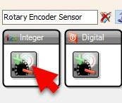
- Add "Rotary Encoder Sensor" component
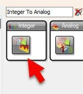
- Add "Integer To Analog" component
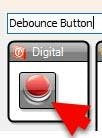
- Add "Debounce Button" component
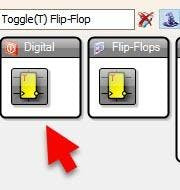
- Add "Toggle(T) Flip-Flop" component
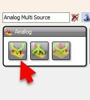
- Add "Analog Multi Source" component
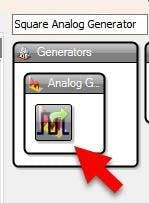
- Add "Square Analog Generator" component
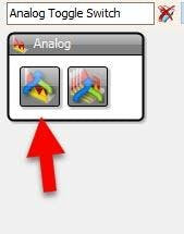
- Add "Analog Toggle Switch" component
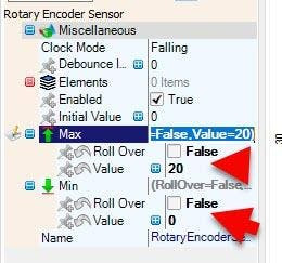
- Select "RotaryEncoderSensor1" and in the properties window:
- set "Max" > "Roll Over" to False
- set "Max" > "Value" to 0
- set "Min" > "Roll Over" to False
- set "Min" > "Value" to 0
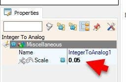
Select "IntegerToAnalog1" and in the properties window set "Scale" to 0.05
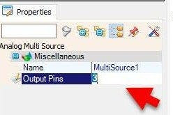
Select "MultiSource1" and in the properties window set "Output Pins" to 3
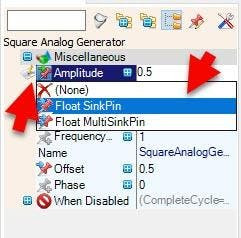
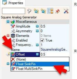
Select "SquareAnalogGenerator1" and in the properties window select "Amplitude" click on the pin icon and select "Float SinkPin"
Select "SquareAnalogGenerator1" and in the properties window select "Offset" click on the pin icon and select "Float SinkPin"
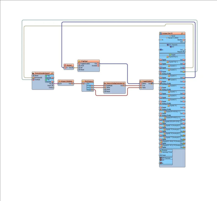
Step 5: In Visuino Connect Components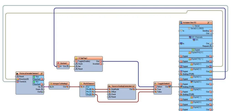
- Connect Arduino.Digital.Digital[ 3 ] OutputPin to RotaryEncoderSensor1 pin [Clock|
- Connect Arduino.Digital.Digital[ 2 ] OutputPin to RotaryEncoderSensor1 pin [Direction|
- Connect RotaryEncoderSensor1 OutputPin to IntegerToAnalog1 InputPin
- Connect IntegerToAnalog1 OutputPin to MultiSource1 InputPin
- Connect MultiSource1 OutputPins.Pin [0] to SquareAnalogGenerator1 pin [Amplitude]
- Connect MultiSource1 OutputPins.Pin [1] to SquareAnalogGenerator1 pin [Offset]
- Connect MultiSource1 OutputPins.Pin [2] to ToggleSwitch1 False InputPin
- Connect SquareAnalogGenerator1 OutputPin to ToggleSwitch1 .True InputPin
- Connect Arduino.Digital.Digital[ 4 ].Output Pin to Button1 InputPin
- Connect Button1 OutputPin to TFlipFlop1 Clock InputPin
- Connect from TFlipFlop1 OutputPin to ToggleSwitch1 Select InputPin
- Connect ToggleSwitch1 OutputPin to Arduino.Digital.Digital[ 5 ] AnalogInputPin (PWM)
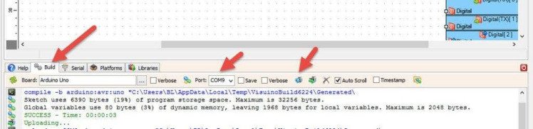
In Visuino, at the bottom click on the "Build" Tab, make sure the correct port is selected, then click on the "Compile/Build and Upload" button.
Step 7: PlayCongratulations! You have completed your project with Visuino. Also attached is the Visuino project, that I created for this Instructable, you can download it and open it in Visuino: https://www.visuino.com
Schematics, diagrams and documents
Code
Credits
Related products


Leave your feedback...