
Wireless Vcr Controlled Over The Internet

Made by iexpress / Artificial intelligence / Communication / Home Automation / Photos & Video / IoT
About the project
Video surveillance has always been a hot topic and implementing ways to keep an eye on things remotely doesn't have to be difficult.
Project info
Difficulty: Moderate
Platforms: Adafruit, Arduino, Everything ESP, Microsoft, Sony
Estimated time: 1 day
License: GNU General Public License, version 3 or later (GPL3+)
Items used in this project
Hardware components

View all
Software apps and online services
Story
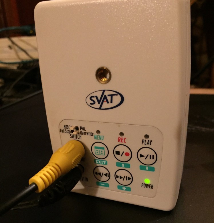
I thought it would be interesting to connect a Sony Spresense with an ESP8266 WiFi module to a VCR to make the VCR controllable over the Internet.
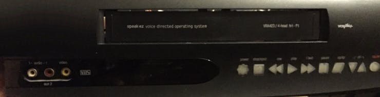 VCR - Video Cassette Recorder
A Sony Spresense main board can be interfaced directly in the recording unit. While I'm using a VCR here, it is possible to do the same with other hardware like a Blu-ray, DVD or Hard Disk video recorder.
First, I decided to add a Composite-to-HDMI video converting card to the VCR's composite output and hot-glued it in place while creating an HDMI output in the back of the unit. Now the unit has both Composite and HDMI output.
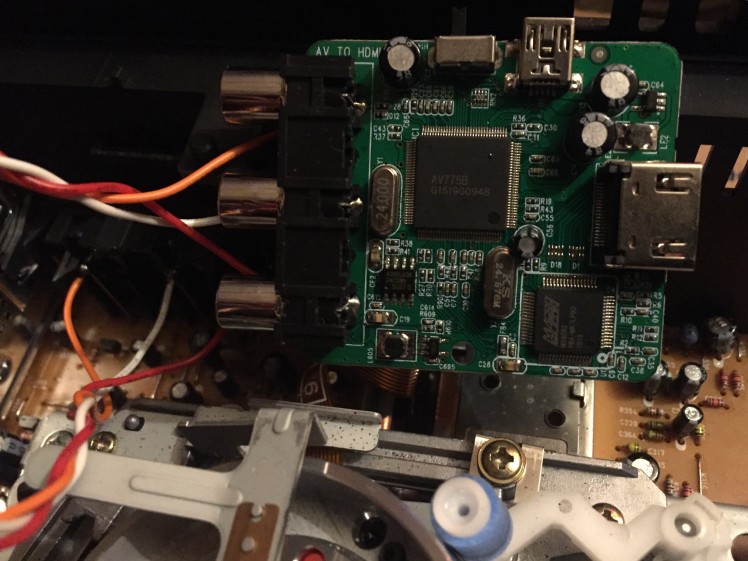 1 / 3 • CVBS to HDMI Converter wires soldered to VCR video/audio output
Then I removed the front panel cover and soldered ten jumper wires to the positive sides of each button from the VCR's front control panel's circuit board and ran the wires through the front of the frame, tying them together in a group to make them easier to handle.
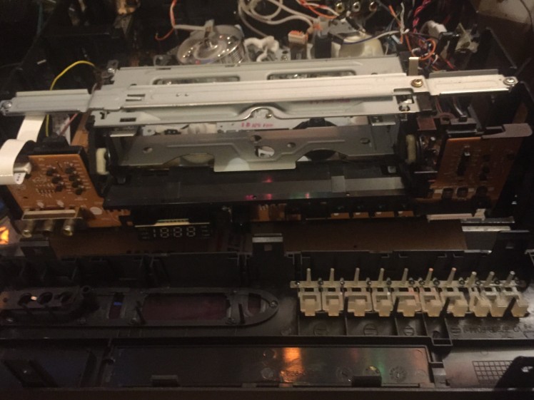 1 / 4 • Removing front panel cover
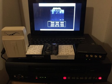
Next, I assembled both Sony Spresense Main and Extension Boards together and uploaded the bootloader to the Spresense Main Board with the Arduino IDE to get it ready for operating as a hardware controller.
 Spresense Main & Extension Boards
Then I wrote a quick sketch to turn the VCR on and off every half second to demonstrate that automated remote control was possible with the Spresense boards.
 1 / 2 • Turning the VCR On
Next, I wired up all of the front panel button wires to the Sony Spresense Extension Board between pins 2 and 11 while keeping track of which wire went to which button on paper.
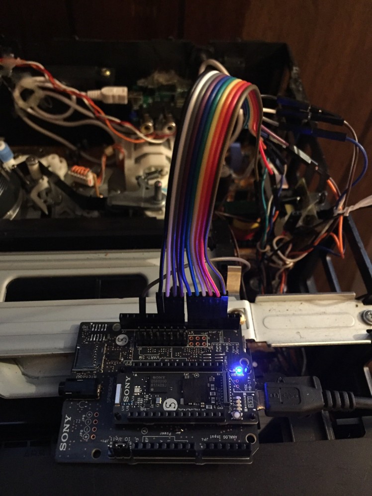 Sony Spresense Main and Extension boards interfaced with VCR buttons
Afterwards, I decided to stop the automated process and control the VCR manually by sending chars over to the Spresense Main Board via keyboard in the Serial Monitor of the Arduino IDE at 115,200 baud rate.
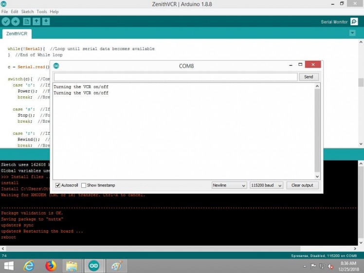 Turning the VCR On and Off
Logically, the next step was to test all of the buttons to see if the correct messages were being returned to the Serial Monitor.
Here we can see that all ten messages came through without any errors. We'll also be making sure that the actual VCR functions are being triggered when keyboard characters are sent.
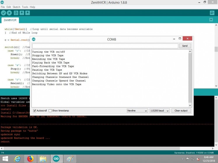 All ten commands returning status messages
With the last instruction from above being sent to the VCR, it started recording just fine after sending the keyboard character 'v' for the video recording command.
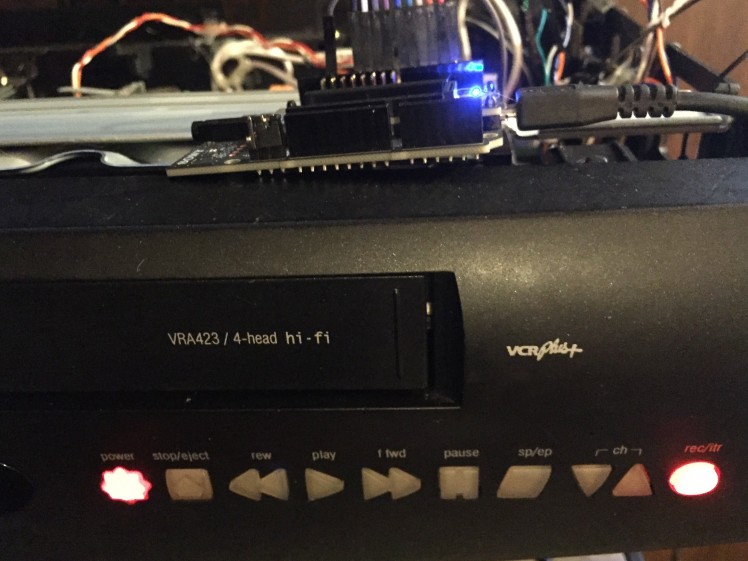 VCR recording video
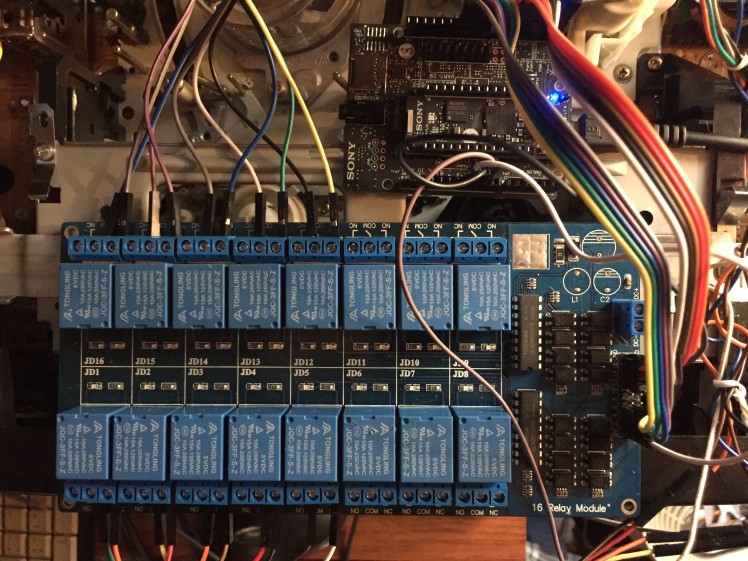
Though sometimes it didn't seem to trigger the VCR functions correctly all the time, I added a 16 channel opto-isolated relay board to the circuit and can use the very same Arduino sketch without making any changes to trigger individual relays instead to keep the VCR buttons in their natural state until they are selected in order to avoid any potential conflicts that may occur in the VCR hardware.
 Spresense connected to opto-isolated relay trigger inputs
Pretest: Controlling 16 Channel Relay Board with Sony Spresense
Spresense connected to opto-isolated relay trigger inputs
Pretest: Controlling 16 Channel Relay Board with Sony Spresense
Now I'll use ten male-to-male jumpers to connect all the VCR button wires up to all the COM inputs of the relays I'd like to use.
Here, I used relays JD12-JD16 for Spresense pins D02-D06, and relays JD5-JD1 for Spresense pins D07-D11:
 Button wires hooked up to relay board COM pins
Now I'll connect the Normally Open side of each relay to ground, but will have to make a small circuit board with 12 pin headers on it to run over to one of the relay board's ground pins via a linear solder bridge.
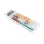
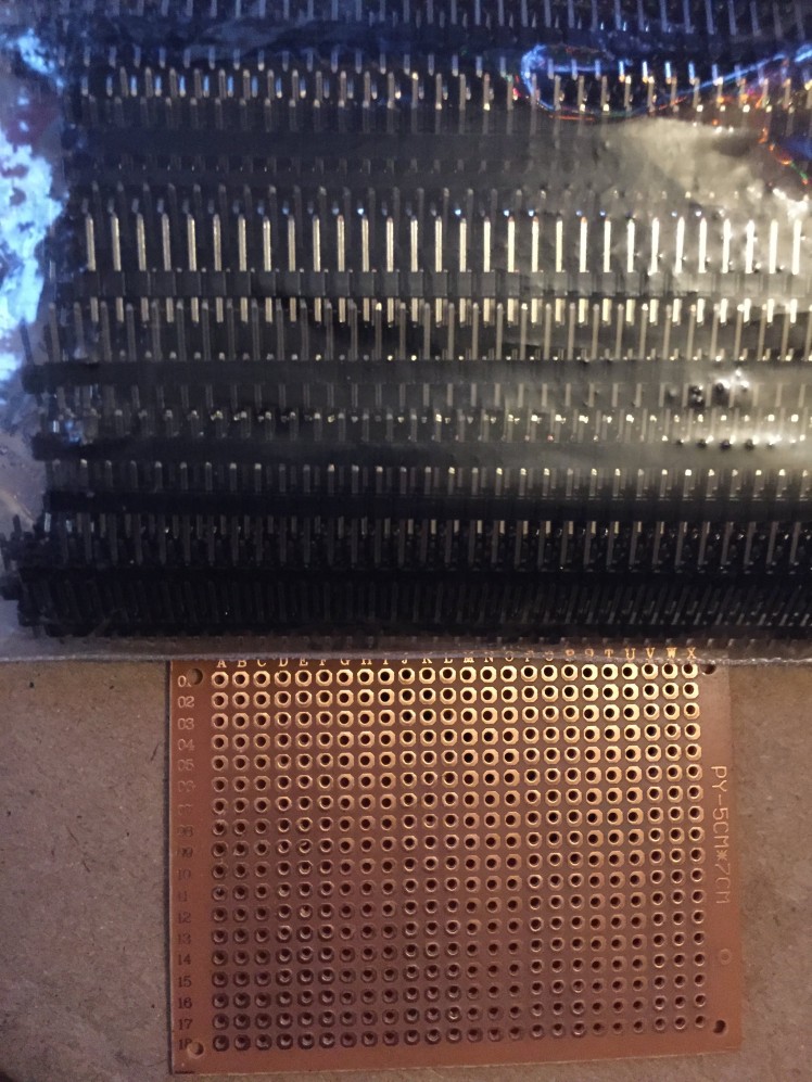 1 / 3 • Step 1: Gather pin headers and a small perf board
After assembling the small circuit board providing the solder bridge, I then connected the Normally Open side of each relay to it and then ran another wire from it to one of the relay board's ground pins.
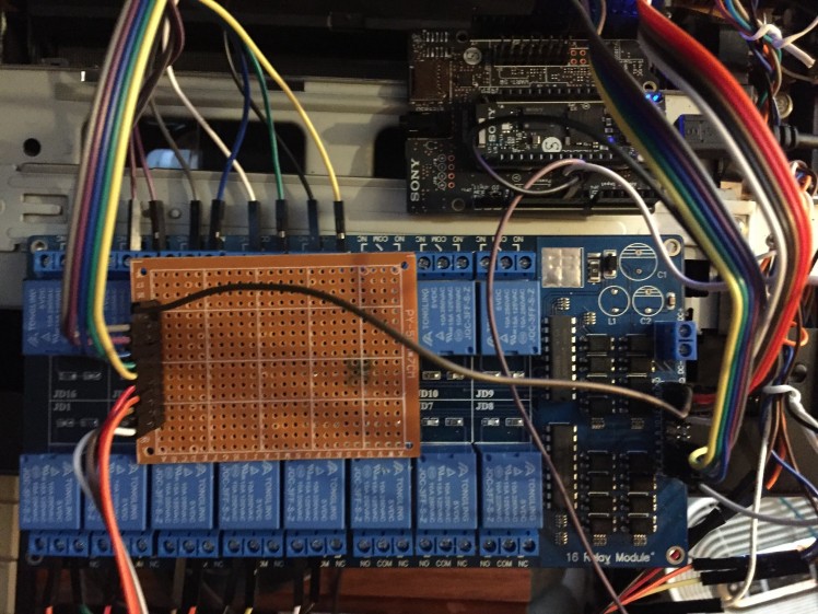 Normally Open sides of relays connected to a linear solder bridge on a circuit board that leads back to the relay board's ground
Testing the buttons again through the Serial Monitor in the Arduino IDE shows that all ten of the buttons are functioning properly with 0% error and each relay holds the button wire low for 200ms.
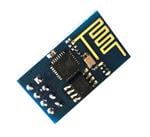
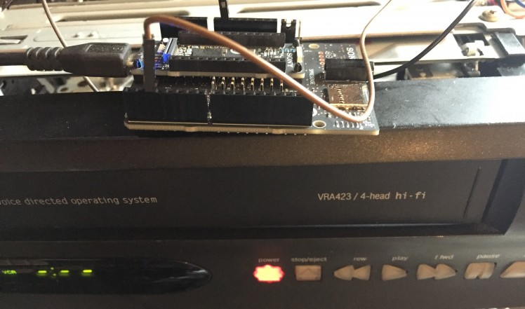
With the VCR functions working, I then moved on to hot-glue an ESP8266 WiFi adapter onto the VCR frame that I interfaced with the Sony Spresense Extension Board that another wifi module will connect to.
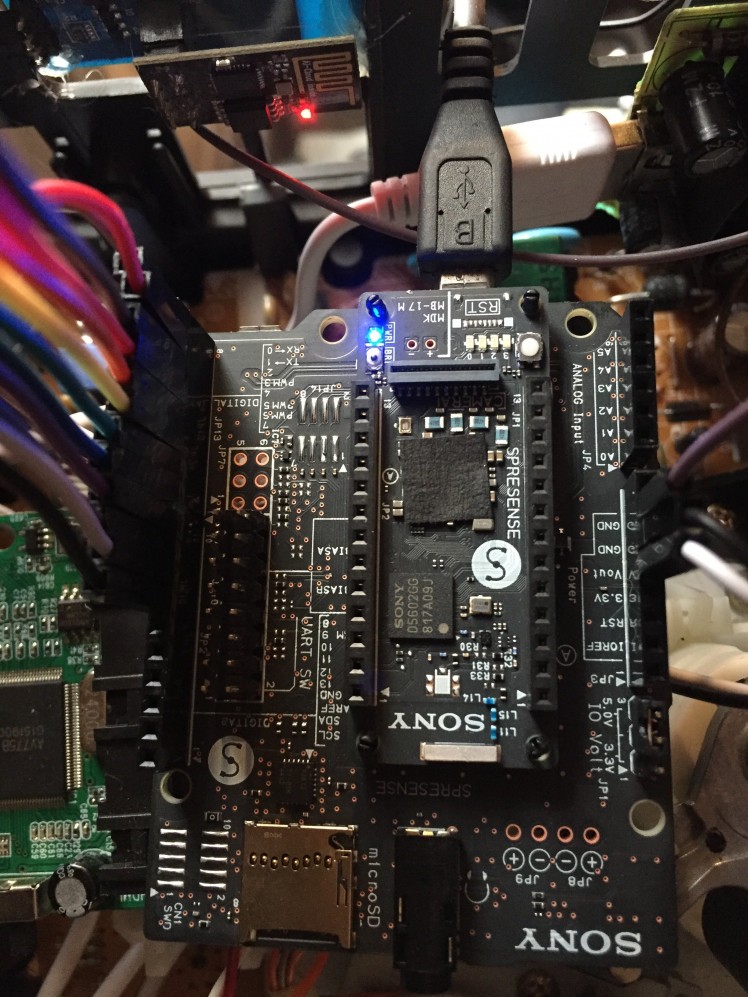 ESP8266 wifi module interfaced with Sony Spresense.
Then I connected another ESP8266 module to the computer using a USB to ESP8266 adapter. Linking the two modules together will take place in the Serial Monitor of the Arduino IDE.
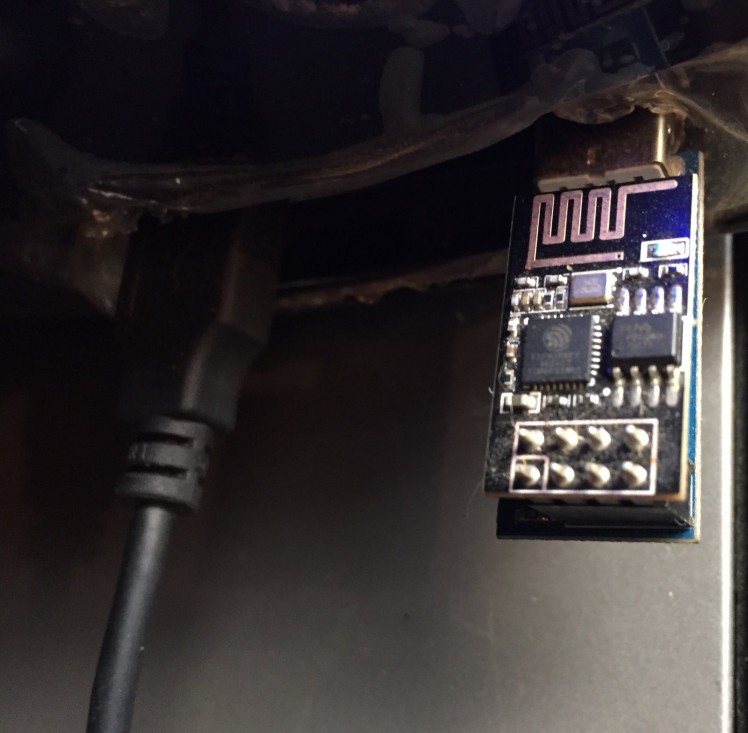 USB to ESP8266 module and adapter
Inside the Serial Monitor of the Arduino IDE, I used the ESP8266 that's connected to the computer to connect to the one in the VCR by asking it to join an access point named "Otter Box". After it connected to the one in the VCR, it gave me get an OK message and now we can leave the Arduino IDE to do other things.
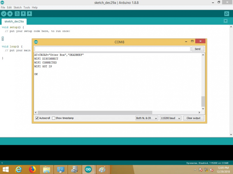 Connecting one ESP8266 WiFi Module to Another in the Arduino IDE.
After testing USB and ESP8266 communication through the Arduino IDE's Serial Monitor, I built a VB.net app to control the VCR from a local computer before making an ASP.net webpage.
This will come in handy as the ASP.NET webpage that will be hosted will have VB.NET Server-Side code. Once I get button presses working here, it will be a matter of just duplicating the VB.NET code inside an ASP.NET project.
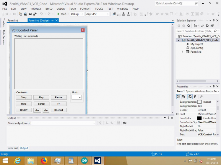 VB.NET VCR Design Editor
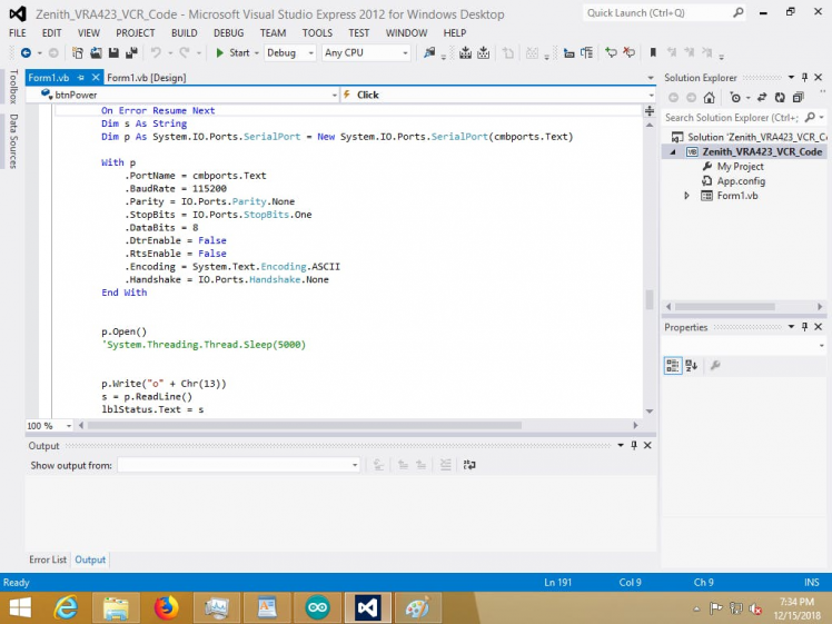 VB.NET VCR Code Editor
Testing the buttons out on the computer via the VB.NET app, we can see that the buttons do in fact work and trigger the appropriate VCR functions correctly. The VCR is now computer controlled.
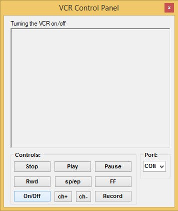 1 / 3 • Turning VCR On and Off
Testing out all VCR functions with a computer, relays and Sony Spresense
1 / 3 • Turning VCR On and Off
Testing out all VCR functions with a computer, relays and Sony Spresense
With the buttons working to control the relays that control the VCR functions, we can now build an ASP.NET webpage to make the VCR viewable and controllable over the internet.
Building a webpage to host our video feed is relatively simple. First we open Visual Web Developer 2008 Express and design our graphics, laying out buttons and a few other controls and then we can add our VB.net button code to the ASP.net project.
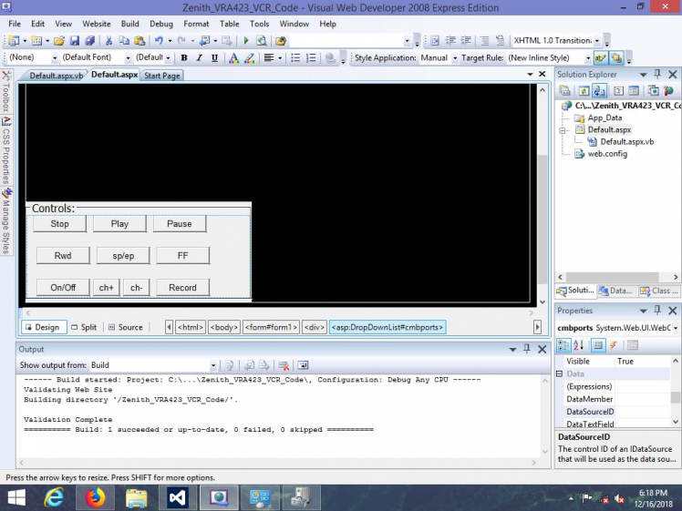 ASP.NET Design Editor
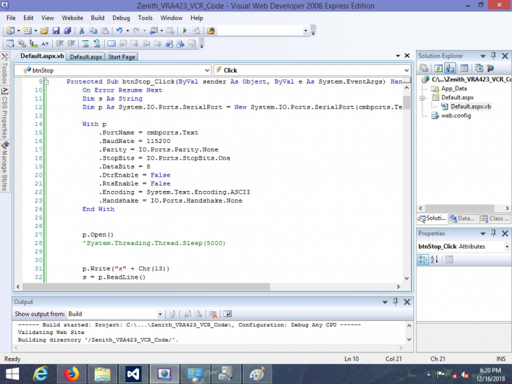 ASP.net Code Editor
After adding all the components and our button code from the VB.net Solution, we can now test out our page locally with the built-in local server to check out the functionality of the buttons.
We will also want to make sure that the VCR is returning the correct messages to our webpage as well as making sure that the VCR actions are being triggered and correspond with the incoming messages.
 1 / 4 • Turning the VCR On
With the buttons on the ASP.net web page working to control the VCR functions, we can now add a live video feed to the page.
First, I connected the CVBS camera up to the VCR's video input which also shows the time and date on the video as an overlay in the composite video signal.
 1 / 2 • CVBS Security Camera
Then I connected the VCR's video output to a standalone video server's input, and then connected the video server to the computer via Ethernet to send our VCR video feed to the computer which will be visible in the ASP.net webpage.
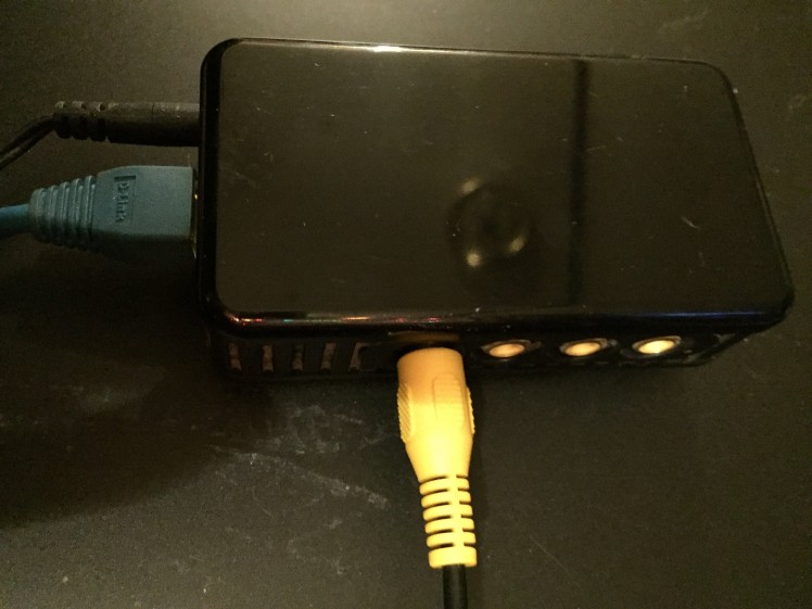 IP Video Network Video Server
Finally, I had to add an Image URL to a picture box in the ASPX source code page to point to the IP address and video stream of the standalone video server which was 169.254.1.13/GetData.cgi.
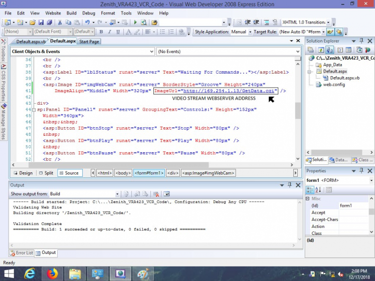 IP Video Network Video Server IP Address added to Source Code
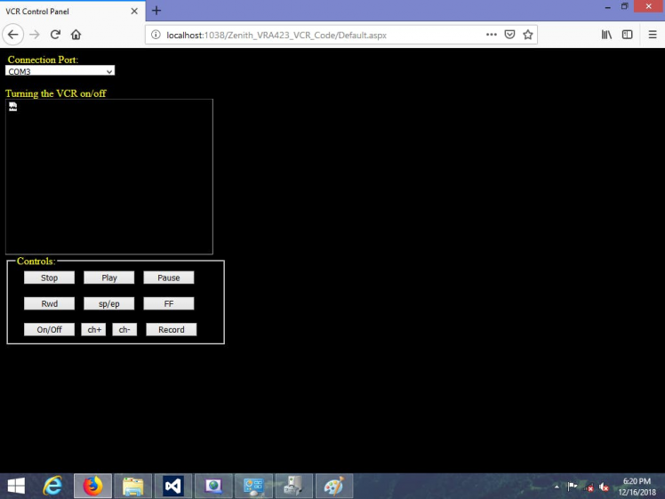
Testing out the ASP.net webpage again shows that all of the buttons are working correctly and that the Image URL works to display video coming in from the VCR.
I also centered the form to place all of it's contents in the center of the webpage.
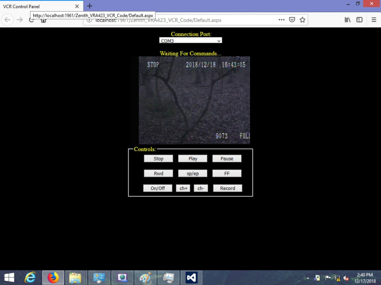 Centered Website
Another step we can take for added security against unauthorized access to the VCR is to add another panel to the ASP.net page requiring a username and password before showing any of the video feed or controls in the VCR panel as shown above to the user.
This is similar to a user login but verification will occur directly inside the server-side code by switching the visible properties of two panel objects in the form between TRUE and FALSE.
Heading back to the Visual Web Developer project, I added another Panel to the web form to create a login feature that requires a username and a password. I placed a couple labels and text boxes inside the panel, naming them txtUsername and txtPassword respectively to make it easy to refer to them in the program code.
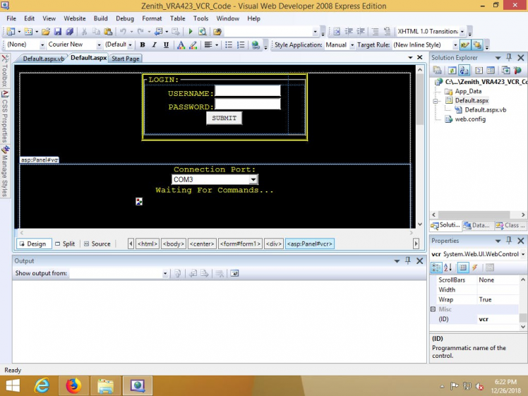 VCR Control Panel Login Panel
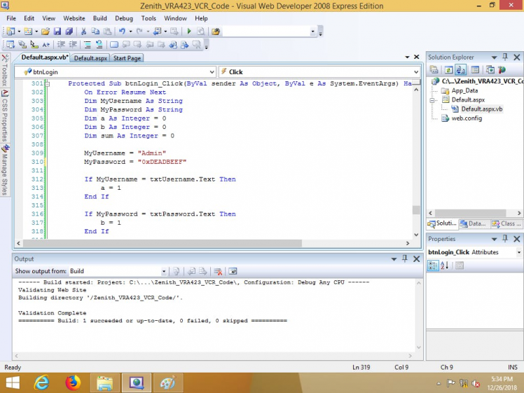 Web Form Login Code
After running the project again through the local web server, we can see that the login panel is visible and the VCR panel is invisible and will remain invisible until the variable named "sum" in our code above equals 2. In my example in the code, the username is "Admin" and the password is "0xDEADBEEF".
In addition, two more variables are added whose values will change if the username equals the value of txtUsername.text or if the password equals the value of txtPassword.text.
Once the value of the sum variable equals 2, the VCR panel becomes visible while hiding the login panel.
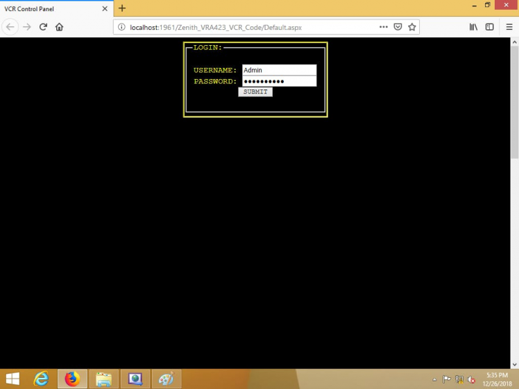 Login Panel is Visible
Here, we are greeted with the Login panel and any visitors trying to view the video feed will have to know the username and password beforehand before they can view the VCR Panel that holds all the VCR controls and status labels along with the video feed. This is a certain way to prevent unauthorized access to the VCR.
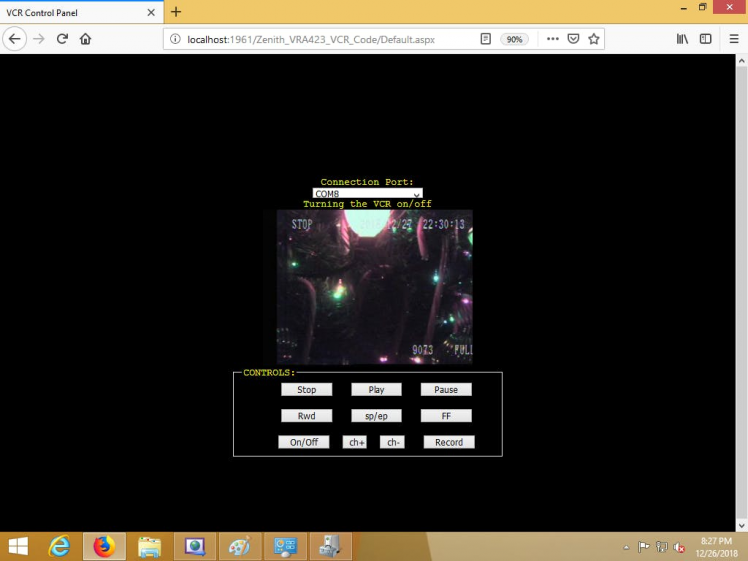
After successfully entering in the correct username and password, the login panel disappears and the VCR panel becomes visible. For testing, I entered in the wrong username and password separately to see if the VCR panel stayed invisible while the login panel only reset the txtUsername and txtPassword text fields.
Additionally, I gave the webpage the ability to save the username along with the date and time in a text file on the server every time a user signs in. The file is only updated when the username and password are correct.
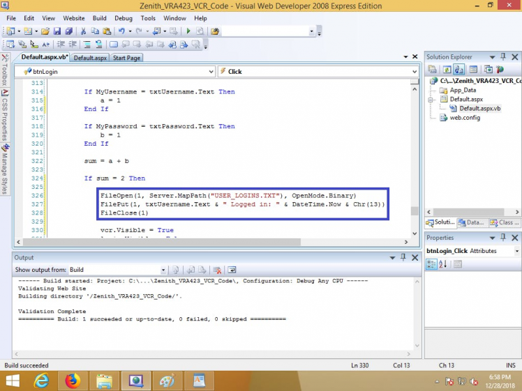 Code that writes the username and date/time info to a file during login.
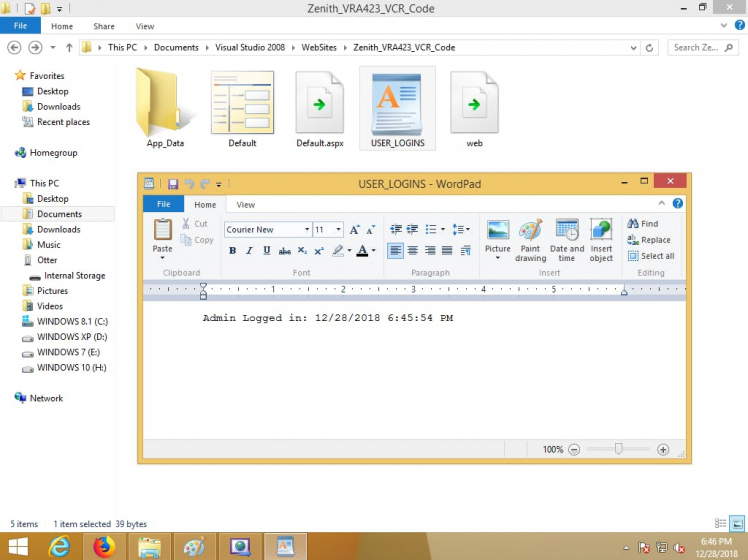 USER_LOGINS.TXT is present in the website's main directory along with it's contents.
All we have to do now is start hosting the webpage with UltiDev Cassini Web Server and then we need to redirect all incoming traffic from the internet side directly to the computer hosting the video feed.
What we do here is point to the local ASPX webpage we want hosted in the web server's explorer to start hosting the webpage. Here are the steps I took:
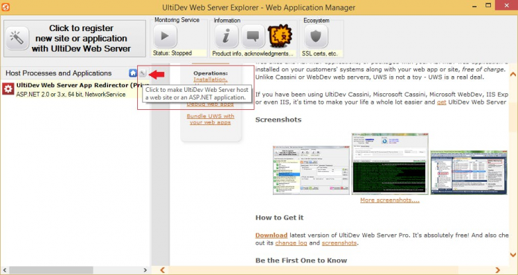 1 / 10 • STEP 1
First, I took a quick look at the Network Connection Details of the Wi-Fi Status of my Wi-Fi Adapter inside the Network and Sharing Center from the Control Panel of Windows 8.1 to find the local IP Address of the computer hosting the video feed.
Then I entered in the router-assigned IP Address of the local computer that is hosting the video feed into the Port Forwarding area inside my router which is listed as a DMZ service.
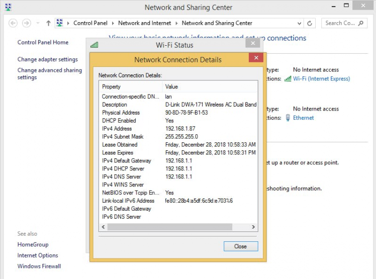 Locating Local IP: 192.168.1.87
 Entering Local IP 192.168.1.87 into the DMZ area of my Router
After adding the local IP Address to the DMZ area of the router, it rebooted and then the VCR became accessible over the internet.
Now I can access the VCR remotely by typing in the IP Address that my Internet Service Provider gave me for accessing the internet from home. For testing, I used Safari web browser on my iPhone while I was away from home at a store and it worked great.
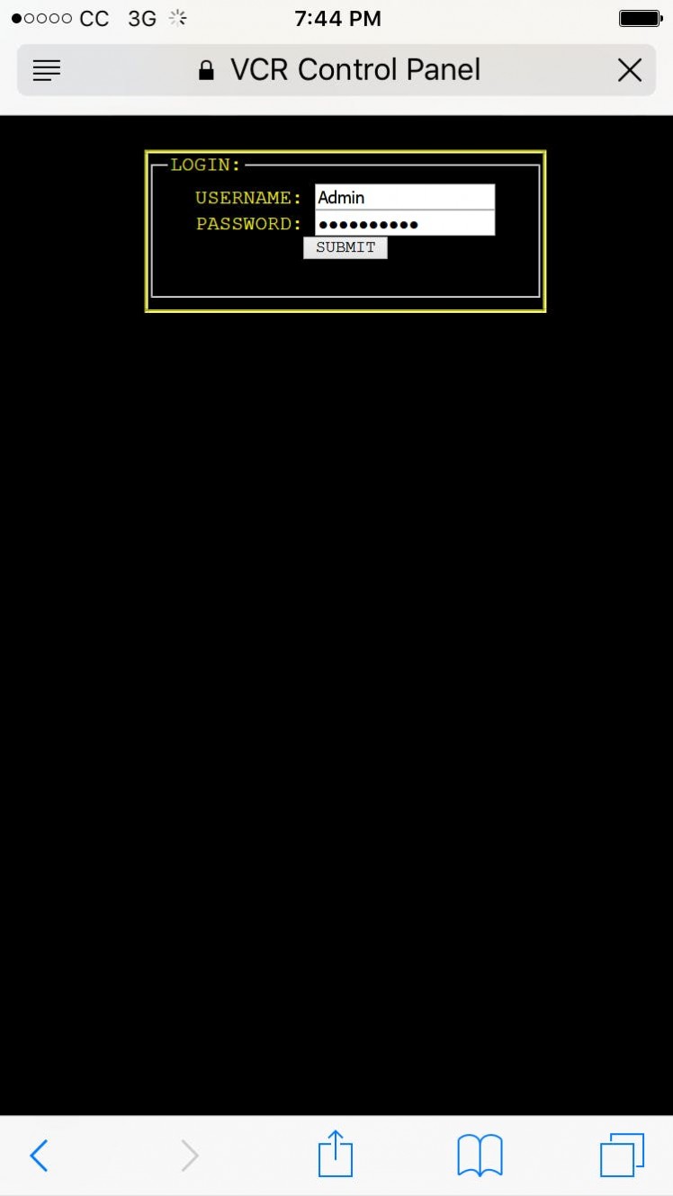 VCR Login Panel in Safari on an iPhone
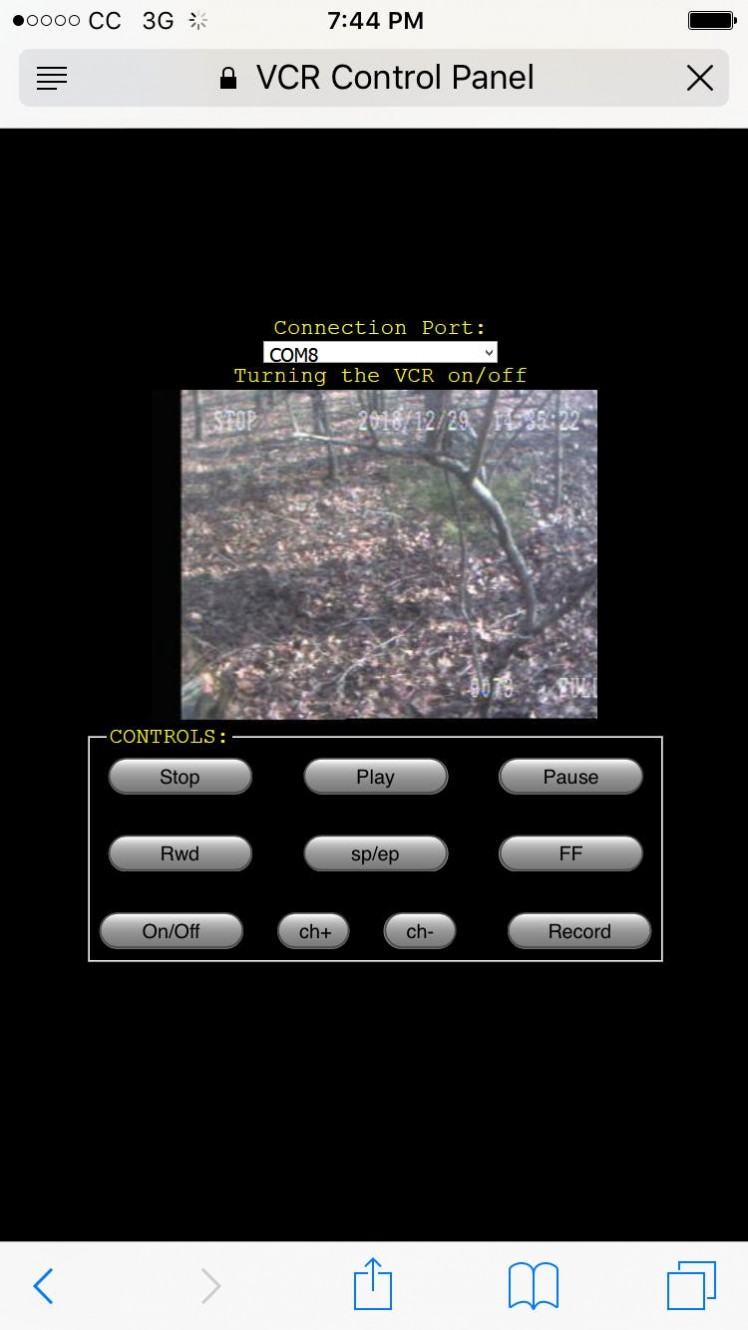 VCR Control Panel in Safari on an iPhone
Now I can access the VCR from anywhere in the world by typing in the IP Address assigned to my internet modem at home into any web browser on any computing device like a phone or laptop along with keeping track of who signs in to view or control the VCR.
In conclusion, this project provides a solution to remote monitoring of a video source while being able to controll all of the hardware functions of a video recording device remotely with simple button presses in a web browser on your phone or computer from anywhere on the world via the internet.
Thank You for reading!
Schematics, diagrams and documents
Code
Credits
Related products


Leave your feedback...