
Weatherbot - A Motorised Weather Machine

Made by DIY-Machines / 3D Printing / Art / Home Automation / Robotics / Weather
About the project
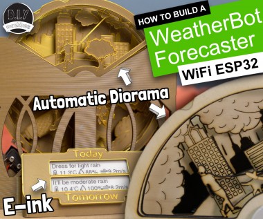
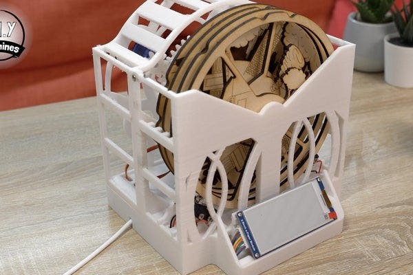
A WiFi connected weather forecasting machine. Shows a hyperlocal weather mechanically on a mini diorama & e-ink display for detailed outlook
Items used in this project

Hand tools and fabrication machines
Story
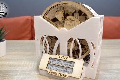
Meet WeatherBot, my WiFi connected weather forecasting machine. WeatherBot retrieves a local forecast from OpenWeatherMaps and then shows you tomorrows weather with a motorised mini diorama. It automatically updates every few hours (you can set your own update interval) and shows a hyper-local forecast based on longitude and latitude.
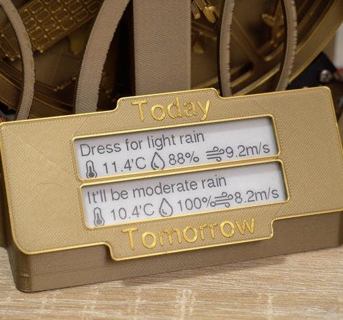
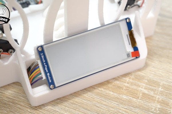
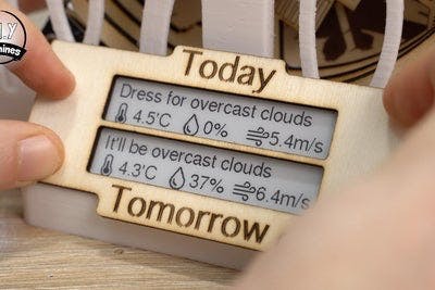
The additional 2.9" e-ink display provides a more precise insight into both todays and tomorrows weather patterns without the distraction and brightness of a more traditional display.
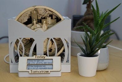
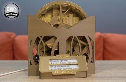
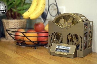
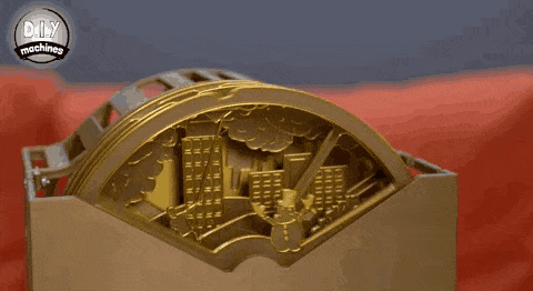
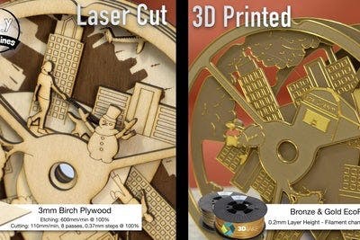
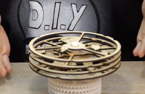
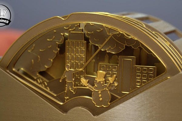
In the photos above you can see two that I built. The white one had its white parts 3D printed and the wooden parts laser cut on my Snapmaker from some 3mm Birch Plywood. Don't worry if you don't have access to a laser cutter, the golden and bronze effect one was entirely 3D printed. ?
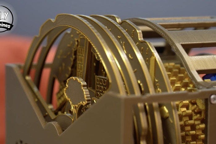
The WeatherBot is powered by single USB cable making it easy to connect wherever you want to see the weathers outlook. The mechanics are driven by four micro servos and I’ve designed the body to be clockwork like whilst allowing you to see the inner workings.
I’ll explain step by step how to make one of your own.
Step 1: Project VideoAs with all my projects I have made an accompanying detailed step-by-step video tutorial. If you would like to see the WeatherBot in action then take a look at the first minute or so of the video.
Don't worry, I will also explain every step for the project in the remainder of this article. I would suggest referring both to this written guide and the video if you ever find yourself a little confused as to what you should be doing whilst assembling your own - though I will be trying my best to be as detailed as possible here for you.
Step 2: BOM (Bill of Materials)
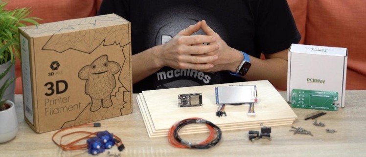
To make one of your own you will need a few items. Here is a list of what I used and where you can find it for yourself online:
- Waveshare 2.9” E-ink Display (296x128): https://geni.us/E-inkDisplay1
- Electrical wire: https://geni.us/22AWGWire
- ESP32 (x1): https://geni.us/ESP32
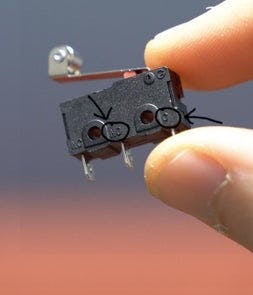
- Limit Switches (x4): https://geni.us/ContactSwitch
- Micro continuous / 360 degree rotation servos (x4): https://geni.us/FS90R
- PCB: https://geni.us/WeatherBotPCB
- USB cable (for uploading code and powering project): https://geni.us/MicroUSBCable
- M2.5x14 Bolts (x12), M2.5x8 Bolts (x7) and Nuts (x10): https://geni.us/M2-5BoltKit
- 90 Degree / Corner Header Pins: https://geni.us/90DegreeHeaderPins
- Filament for 3D printing: www.3djake.com
- 3mm thick wood for laser cut scene discs (x4 A4 size): https://geni.us/3mmPlywood
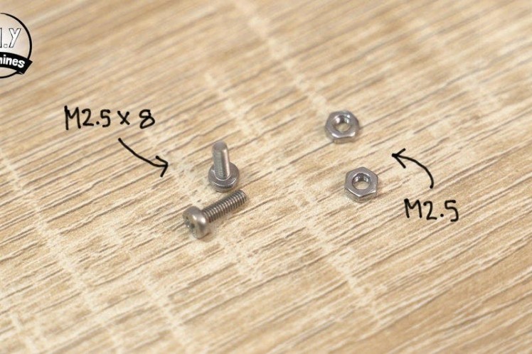
Nuts, bolts and screws needed:
- M2.5x14 Bolts (x12)
- M2.5x8 Bolts (x7)
- M2.5 Nuts (x10)
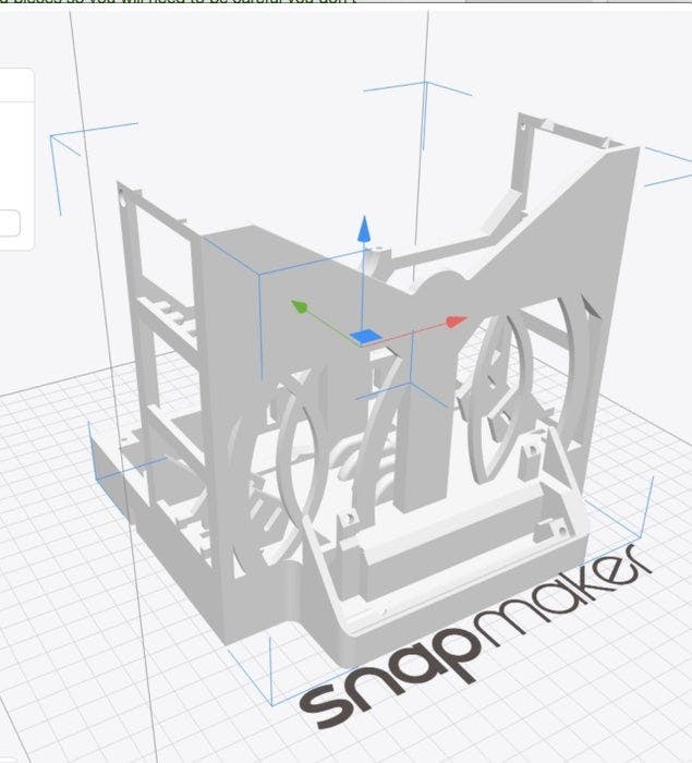
I have uploaded all the 3D printable models and laser cutting files on Prussa's website here: https://www.prusaprinters.org/prints/107501-weatherbot-3d-printable-weather-forecasting-theatr
The first parts which you will need to print are the:
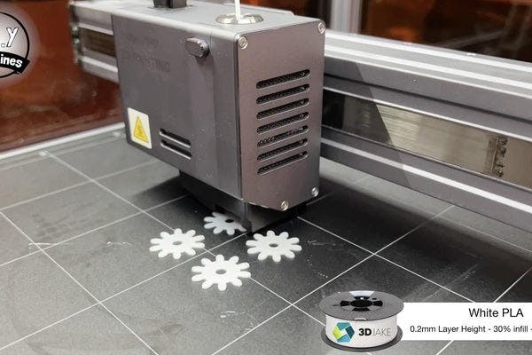
- Four small cogs (Small Cogs.stl)
- The rear section of the main body assembly (Main Body - Back - WeatherBot.stl)
I have designed the parts so that none of the printable components in this project require supports whilst printing. There is some short bridging required (nothing too taxing for a printer) so if your slicer has an option to detect bridging I would enable this.
All of my parts have been printed in PLA plastic. You could also use PETG or ABS if you would prefer if it is what you have to hand already.
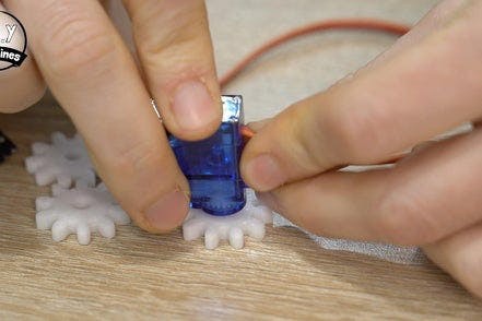
Step 4: Assemble the Servos
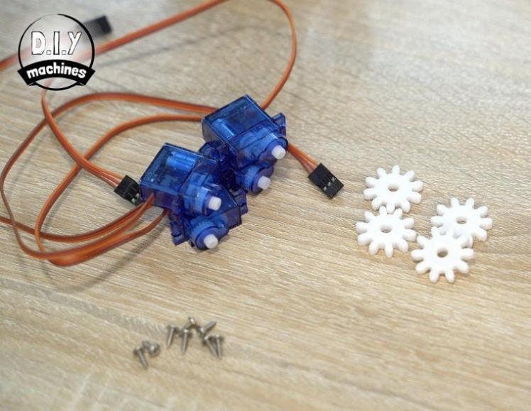
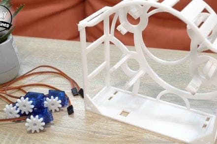

For this step you will need:
- The 3D printed small cogs
- Four 360 degree continuous rotation servos
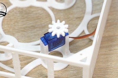
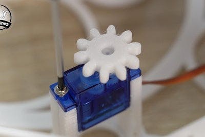
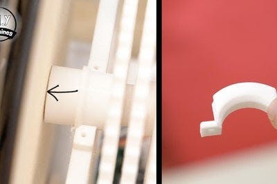
The 3D printed cogs are designed to push fit onto the toothed cog on the top of the servos. It may require some force so I turned the servo over and pushed it down into the cog on the table. If yours go on too easily and you think that they might run the risk of slipping later whilst turning then you could consider carefully applying some glue.
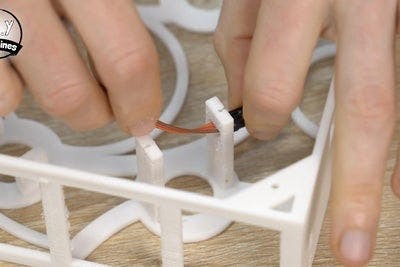
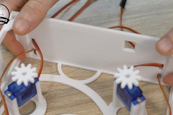
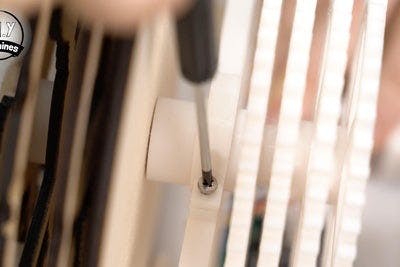
The servos themselves are then fitted into the 3D printed rear frame using their included screws. First pass each servos wire through the cutout in each pair of pillars (this will also naturally show you which way around to orientate the servo). The servo is secured using the screws from above, two for each servo.
After they have been secured the wires from the servos can be passed through the four holes in the bottom of the print as shown in the photo above.
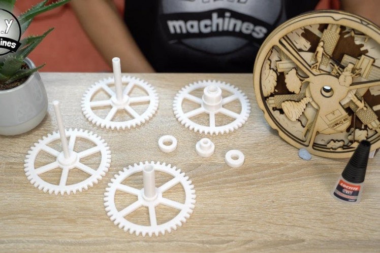
Step 5: Creating the Parts for the Main Axle
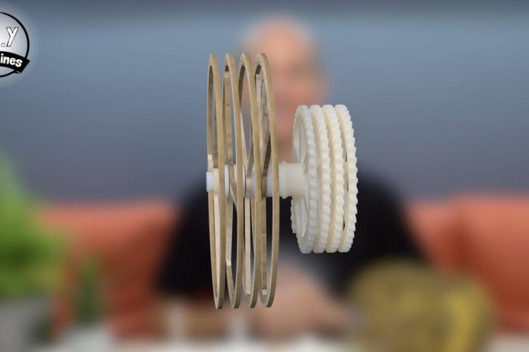
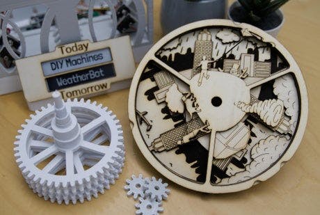
To create the central axle and scene discs we need the following parts:
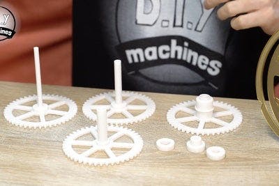
- Spacers (x3 various sizes supplied)
- Large Cogs (x4 various sizes supplied)
- Scene Discs (x4 different designs supplied)
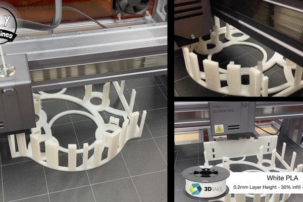
The four large cogs and the three spacers which sit between the scene discs are 3D printed. I increased the infill of these parts from the usual 20% to around 30% to improve their strength.
For the scene discs themselves you have the option of laser cutting them or 3D printing them.
3D Printing the Scene DiscsIf you’re also printing the scene discs themselves then I recommend changing the filament to a second colour 2.8mm into the print. This will show the details of the scene very well as I have done when switching from the Bronze effect PLA to the Gold effect PLA as shown in the photos above.
Laser Cutting and Engraving Scene DiscsSince I have a Snapamaker I swapped its toolhead so that I could then laser cut and etch the scene discs. The discs need to be 3mm thick so I’m using some 3mm birch plywood. I’ve attached the files for laser cutting and etching these parts (the SVG files). Please ensure that when setting up the job in your laser program that the discs are showing as being 160mm in diameter. In some programs they seem to import at a reduced size.
I really like the look of laser cut wood with the burnt marks along their perimeters.
Step 6: Assembling the Main Axle
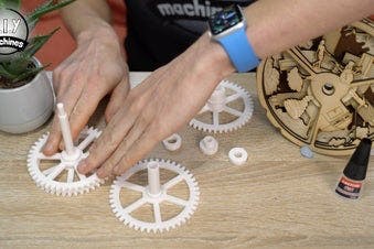
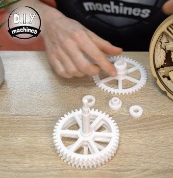
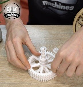

With these parts prepared we can assemble the main axle. Start by passing the four cogs through one another. Start with the one with the longest shaft, thread the second longest over this, followed by the third longest and then the shortest.Give them a spin and check they turn with ease - if not, use some sandpaper to improve the fit.
It is important that they rotate freely without too much friction. Some time spent here will save a lot of work later so only proceed once you're happy with the way they turn.
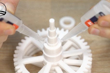
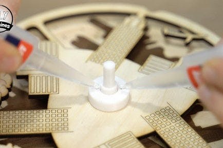
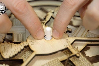
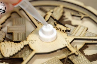
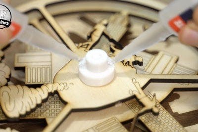
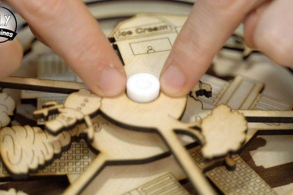
We will be using glue to assemble the remaining pieces so you will need to be careful you don’t accidentally get glue where it shouldn’t be or the mechanism won’t work properly. Add a few drops of glue to the top ledge of the first disc support (which is part of the shortest cog) we can then slide the rain scene disc onto this axle and against the glue. Ensure that it sits horizontal and level as it drys. Its rotation does not matter.
Add the first spacer, the largest one. Apply a couple drips of glue to the gap at the top and the surface of the spacer before adding the cloud cover scene. Again ensure it is level.
Repeat the same with the next spacer and the wind speed disc, then follow this with the last spacer and temperature disc. You will need to allow this to fully cure before using it but check it works after about 30 seconds, if any glue has made its way to where it should not be you might still have time to resolve it before it fully cures. All being good you can set this aside and we can work on the front frame next.
Step 7: Print the Front Section of the Main Body
For the following steps of the build you’ll need to print the main front part of the body 'Main Body - Front - WeatherBot.stl'.
This can be a particular long print and will use about 225g of filament so ensure you have plenty on your roll before you start the print. There is no need for supports but don't forget to turn on ay bridging detection features in your slicing software if it has any.
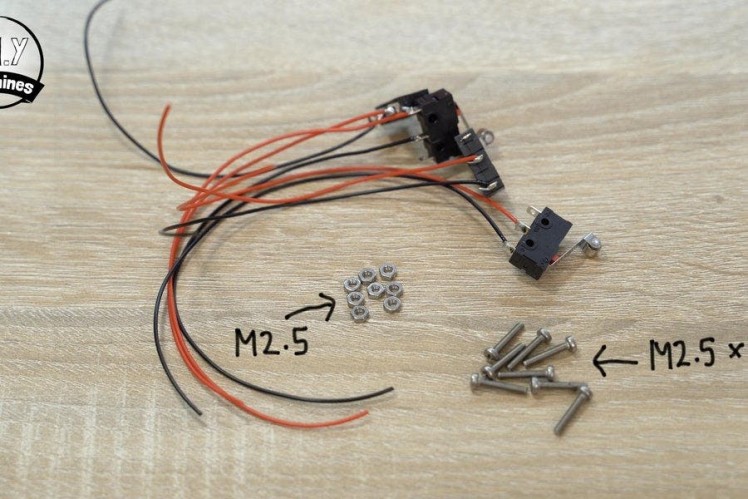
Step 8: Prepare the Limit Switches
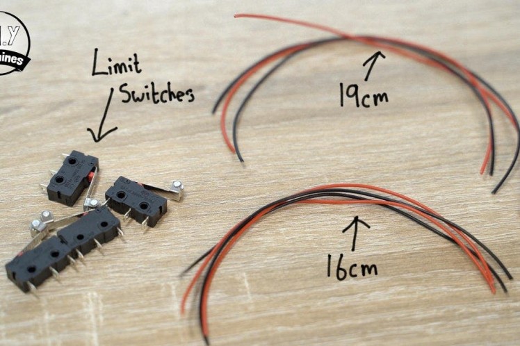
For this step you will need:
- Limit switches (x4)
- Electrical wire
- Soldering iron
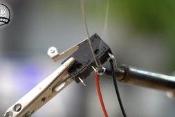
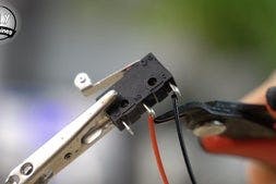
Whilst the front section of the main body prints on your printer (previous step) we can use the time to begin preparing the four limit switches.
We will solder some wires to the normally open and common legs. On mine this is marked with 'C' on the common leg and 'NO' on the normally open leg.
Solder a separate pair of 19cm long wires to the Common and Normally Open legs of two switches, and a pair each of 16cm wires to the same legs on the other two remaining switches.
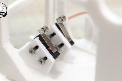
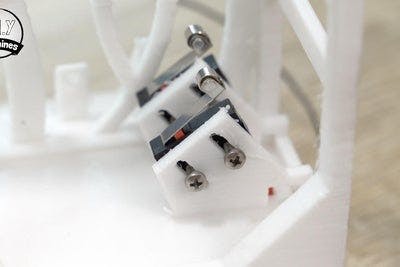
Step 9: Install the Limit Switches
For this step you will need the following:
- The four limit switches we just soldered wires onto
- M2.5x14 Bolts (x8)
- M2.5 nuts (x8)
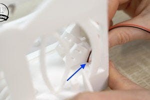
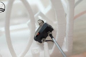
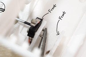
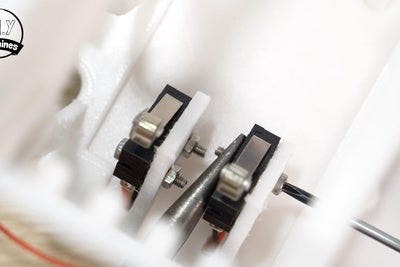
We are going to bolt these inside the main printed part. The two switches with the longer wires will be going on the left hand side of the print as seen from the front.
Feed the wires for each switch through the holes adjacent to their locations on each fin. Install each switch so that the roller is towards the top and the switch itself is on the front face of each fin.
We can then use a pair of M2.5 x 14mm bolts and nuts to secure them.
For easy access I also recommend threading the bolt from the outside and adding the nuts on the inside. This way we can tighten them later by inserting a screwdriver from either the front side or rear of the project. Don’t over tighten them, leave them slightly loose for now. We will also leave them at the bottom of their available travel in the slots, later we will adjust their heights when we tune the machine.
Once added we can flip the print upside down and continue threading the wires through their respective tunnels on the underside.
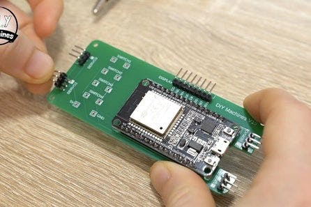
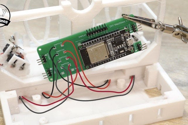
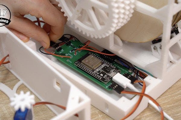
Step 10: Preparing the PCB
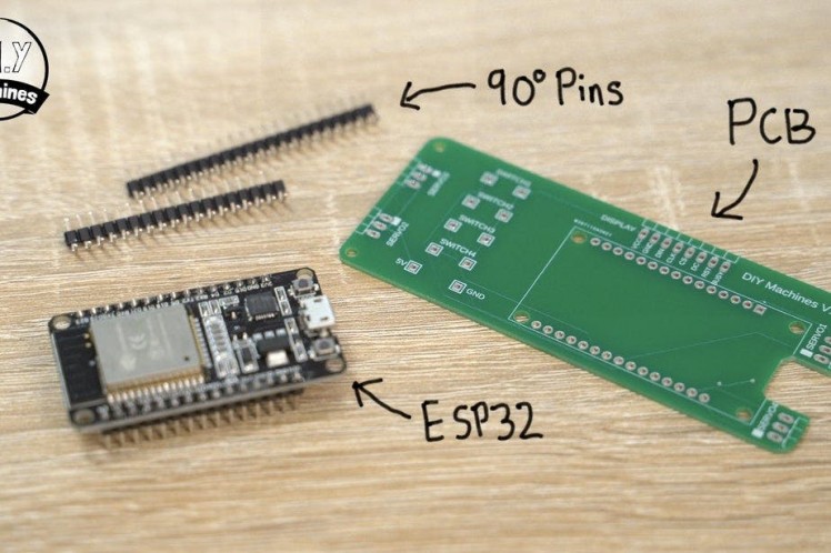
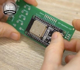

For this step you'll need:
- An ESP32
- Some 90 Degree Pins
- Projects PCB (Optional but makes everything much easier)
I’ll be using the PCB I designed for the project as it makes everything much easier to assemble. You can order your own PCB directly from PCBWay (see the link in the Bill Of Materials at the top) and sometimes I have spares listed on my Etsy shop so it might be worth looking there: https://www.etsy.com/uk/shop/DIYMachines
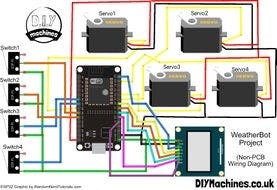
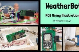
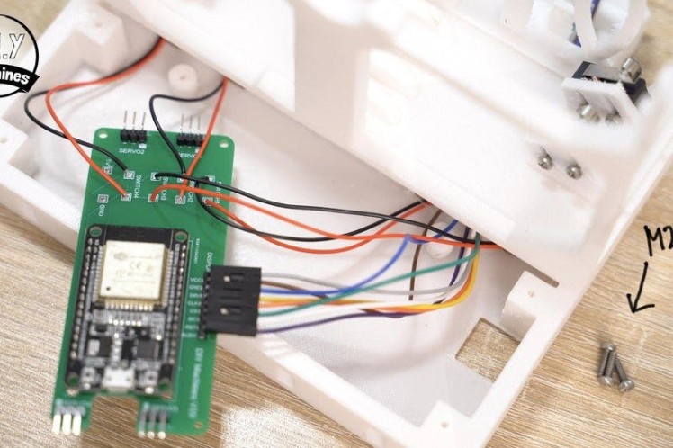
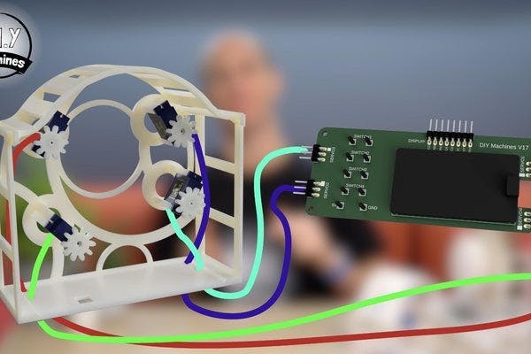
I have included two wiring diagrams in the photos for this step as well. One showing you an overview of how the PCB is wired, which I'll also be explaining over the next few steps in this article. The second shows you how to the make the connections without a PCB if you wanted to go down that route.
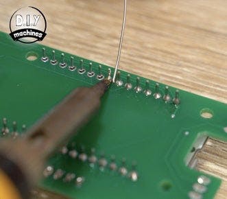
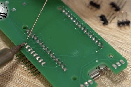
So to assemble the PCB, we can start with the ESP32. This sits over the main area as marked out on the PCB with its USB board over the cutout so that we can connect a USB cable later. Gently push its legs through the PCB and then turn the PCB over and solder the legs in place on the reverse.
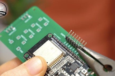
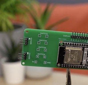
Next are the 90 degree pins which we will connect the servos and display to later, they need to be added to the 5 groups of oval pads around the edges of the board. Four groups of three (two at each end) and one strip of 8 along the edge.
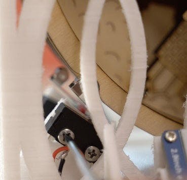
Step 11: Connecting the Switches to the PCB
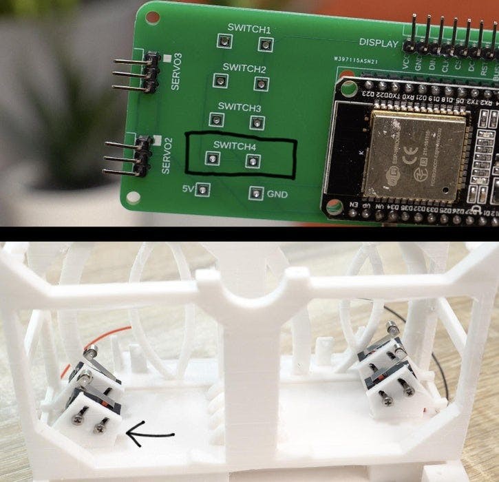
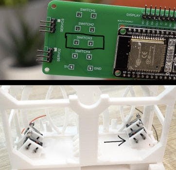
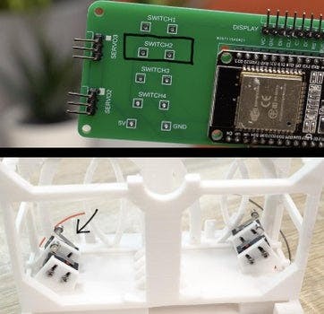
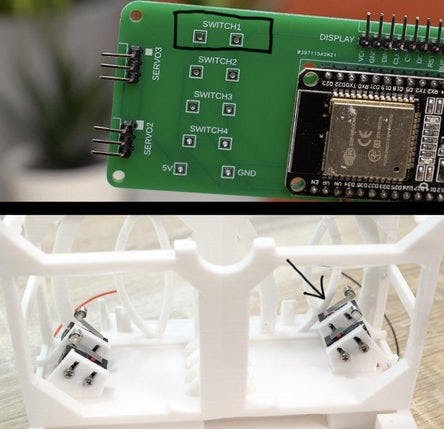
We have four limit switches already installed on our WeatherBot and these need to be connected to the PCB in a certain order.
On the PCB itself you will see four pairs of soldering through holes, numbered Switch 1 through to Switch 4 (with their two through holes directly beneath the label). The switches themselves are numbered from the front of the machine towards the back (though they have nothing printed on them) with the switch closest to the front being number one and the switch closest to the rear of the machine being number four.
With each individual switch though, it does not matter which wire for that switch goes into which one of the two holes on the PCB.
Pass the wires through through the PCB and solder from the other side.
Step 12: Connect the Display

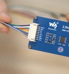

For this step you will need:
- Waveshare 2.9" E-ink display
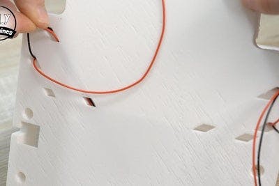
Connect the included wiring harness to the Waveshare display and then thread the female Dupont style connectors though the tunnel to the left of where the display will be installed at the front of the WeatherBot.
Once the wires are though the tunnel they can be connected to the corresponding pins on the PCB. You can tell which goes where by looking at the labels on the display, following the coloured wire and then connecting it to the identically labelled pin on the PCB.
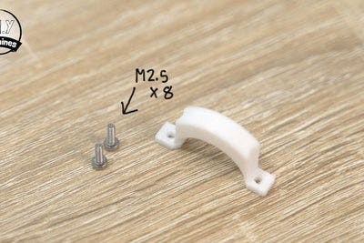
Step 13: Mount the PCB
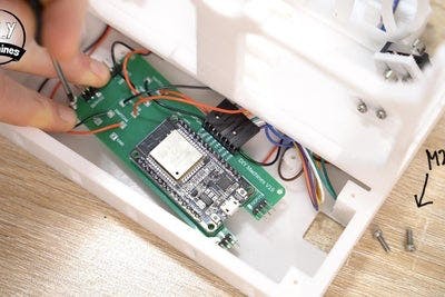
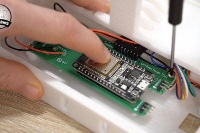
For this step you will need:
- M2.5x8mm bolts (x3)
The PCB can then be secured in place using three M2.5x8mm bolts. It is fitted on top of the three stand-off pillars. Be careful when tucking away the wires which go to the display that you do not damage any of the pins.
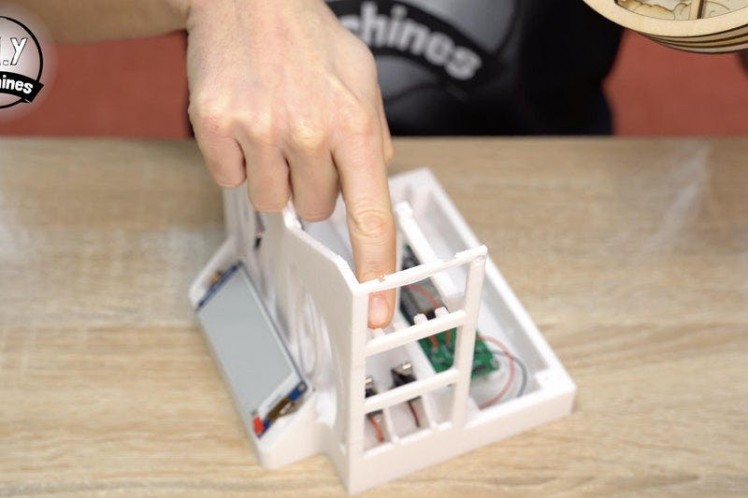
The display is then simply pushed into place on the front of the project. It will be held down securely later on when we install the front cover. We won't be doing that yet until we have uploaded the code and verified all of our electronics work as expected. (You may need to be able to remove the display to check connection if it does not work as intended later).
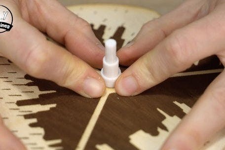
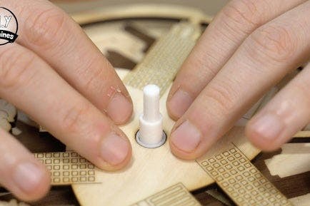
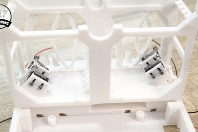
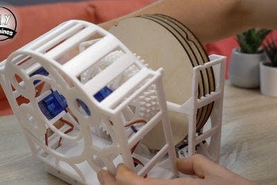
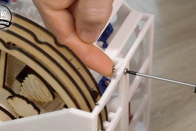
Step 14: Install the Main Axle
For this step you will need:
- Main Axle we assembled earlier and set aside
- 3D printed Axil Cap 'Axle Cap.stl'
- M2.5x8mm bolts (x2)
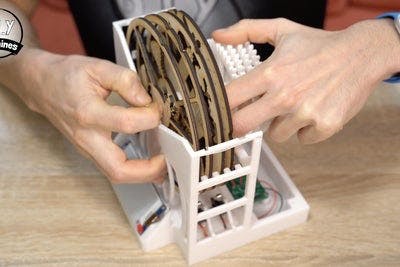
Bring back the main axle so that we can fit it in place, align the four discs with their respective slots - these are made up by the fins protruding from the sides and base of the print (see the first photo).
You can then gently push/pull open the front frame so that the front of the shaft can fit into the recess at the front of the main print. Once it is in place check that the discs can turn freely. If they can, then the 3D printed axil cap is bolted into place with two m2.5 x 8mm bolts over the centre of the axle between the cogs and scene discs. One face of the axle cap is chamfered, this side should go against the matching chamfer on the axle so that it faces the scene discs.
Step 15: Tune Switch Positioning
Now we have both the discs and switches in place we can begin to tune their positioning. Take one disc at a time and rotate the scene disc by hand so that one of the notches on its perimeter passes upwards against the roller. For example the front disc should be rotated clock wise.
Listen for the switch to see if it engages and disengages properly as the notch passes (it will make a quiet clicking noise).
If it does not you will likely need to adjust the distance the switch is from the disc:
- Slightly loosen the bolts holding it in place.
- Move the switch closer or further away.
- Retighten the bolts.
- Check again.
Keep adjusting it until the switch only disengages when it passes a notch. Repeat this process for all four discs.
Step 16: Connect the USB Cable
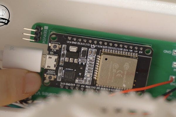
Whilst we still have easy access to the ESP32 we can connect the USB cable. We will use this to upload the code shortly and to power the project once we are finished.
Whilst I can still draw your attention to it easily, I also want to point out to you the Boot button on the ESP32. You will need to press this later when we are uploading our code. ??
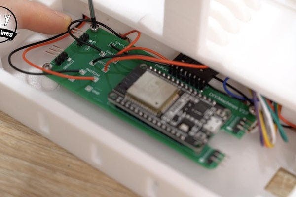
Step 17: Connecting the Servos
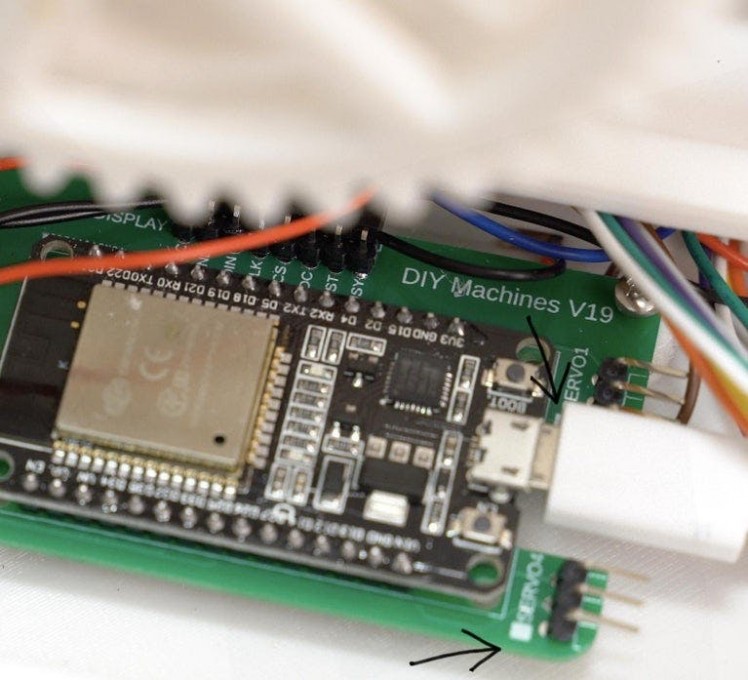
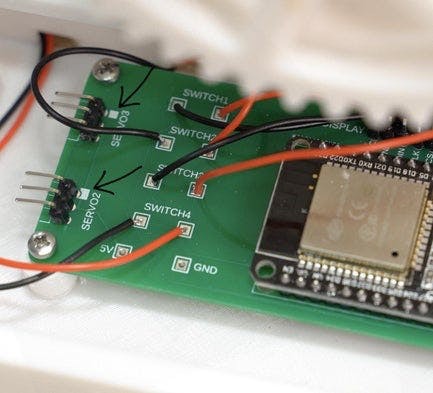
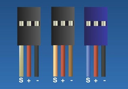
On our PCB I have included a little white mark next to the each set of three pins for the Servo connections. This is here to indicate which pin is the signal pin. You need to ensure that your servos signal wire connects to this pin.
On my Servos the signal wire is the orange wire. I have included the three most common servo wire colour combinations in the image attached and marked which wire is the signal wire for you. If yours does not match the most common three then take a look at the servos data sheet or turn to Google.
As with the limit switches, it matters which servos is connected to which of our servo connections on the PCB. The numbering matches that of the limit switches. So servo 1 should be turning the cog which rotates the scene disc being monitored by switch number one. Again, I have created a graphic above which shows you which servo is connected where on the PCB.
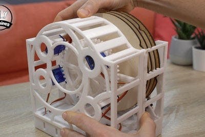
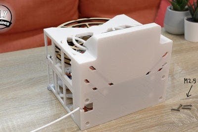
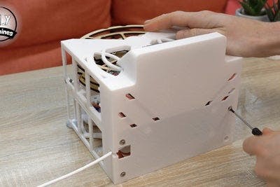
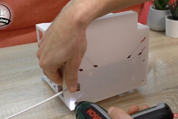
Step 18: Join the Two Halves
For this step you will need:
- M2.5x8mm bolts (x2)
- M2.5 nuts (x2)
- M2.5x14mm bolts (x4)
We will join the two halves of the main body together now. To do this carefully slide the mini cogs and servos around the larger ones whilst watching they don’t get caught. It’s a bit like a physical puzzle. You should also keep an eye that the servo leads do not get caught up at the bottom of the print. There are no moving parts below the base so any excess wire can be tucked away using a screwdriver to push them into the space around the PCB as you bring the two halves together.
Use the two pairs of 8mm m2.5 bolts and nuts at the top on each side to hold the two printed halves together, and then four 14mm m2.5 bolts through the bottom of the enclosure.
Step 19: Uploading the Code
As we will be gluing the display cover in place during the next step it will be good idea to upload the code and check the display works as intended first. Before you upload the code there are a few things you will need to do:
- Install additional Board Manager
So we can then
- Install ESP32 boards
- Install required libraries:
- Arduino_JSON by Arduino
- Adafruit GFX by Adafruit
- ESP32Servo by Kevin Harrington and John K. Bennett
- GxEPD2 by Jean-Marc Zingg
- Get a free OpenWeatherMap API key and a location ID for where you would like to report the weather for.
- Enter your own wifi credentials
All of this I have written out in detail on my website, DIYMachines.co.uk. I have done it this way so that there is a single place I can keep the software instructions up-to-date (for the benefit of this article, Youtube, and many more sites) if additional features are added or corrections need to be made. ?
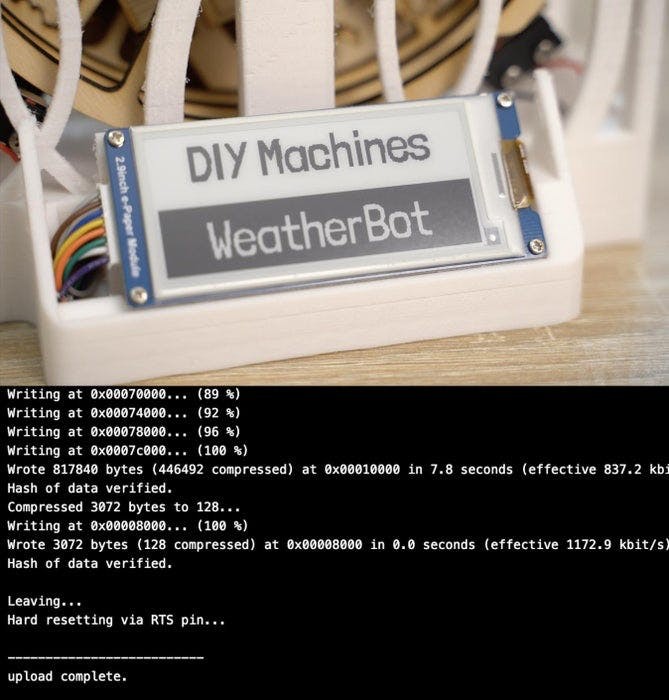
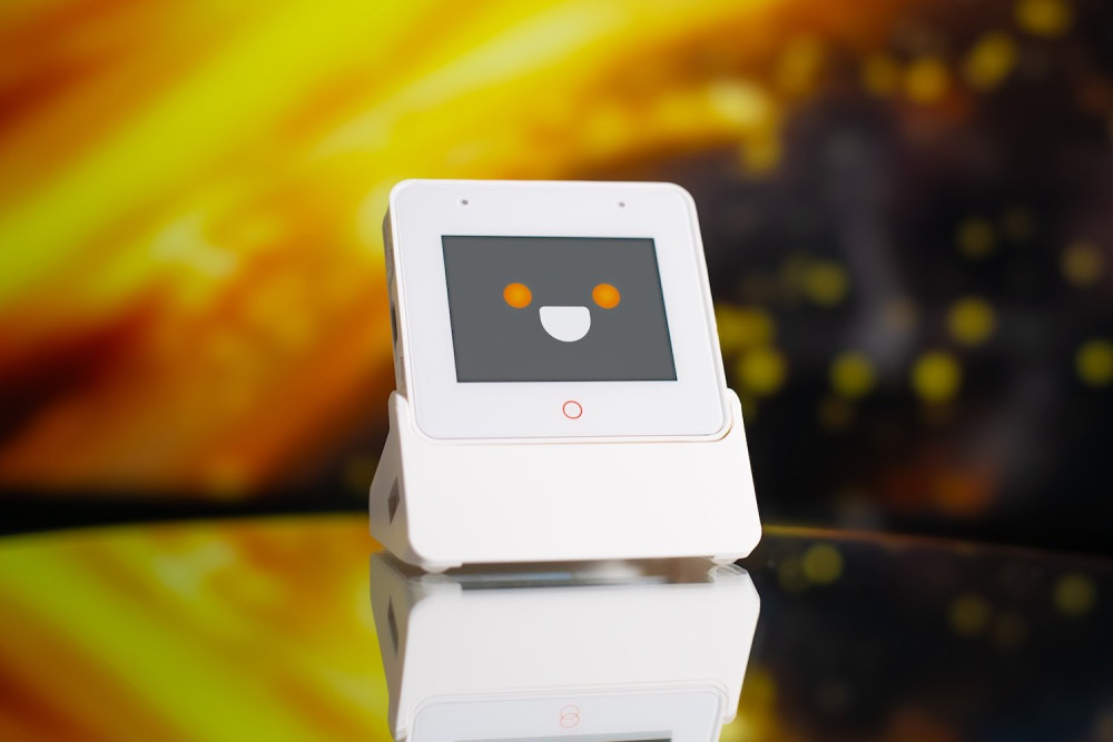
Once you have finished following the programming steps on my site and the code has finished uploading the DIY Machines WeatherBot splash screen should show on the display. If it does than the display is connected properly and we can finish fitting its enclosure.
Step 20: Finishing the Display
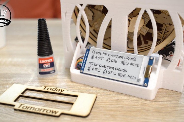
You have a choice of two different Display covers, either a 3D printable one or a laser cut one.
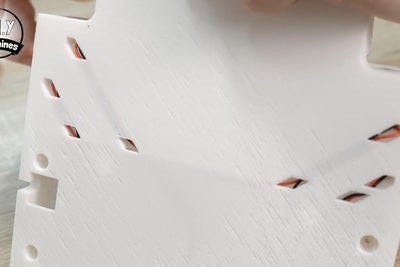
The file for the laser cut cover 'Display Cover.dxf' only contains the cutting pattern. You will need to add your own engraving for the words 'Today' and 'Tomorrow' as shown in the photos above.
The 3D printed display cover looks best with the filament being changed to an alternative colour at 2.8mm into the print - the same technique we used for the scene discs.
Whichever cover you choose to make, it is simply held in place with some super glue in the corners.
Step 21: Self Calibration / Homing

We've now finished building the WetherBot. So how will you know it's working?
When it first powers on you will see the DIY Machines splash screen, at this moment in time the WeatherBot is attempting to connect to the WiFi network and retrieve a weather forecast from the OpenWeatherMap service.
The scene discs will also start to rotate one at a time. The machine is looking at each disc in turn and timing the duration between the notches on the perimeter of each disc as they pass the limit switch. It can use this information to figure out the orientation of each disc (thanks to the two closely spaced notches the machine is looking for).
Once this has been determined and the weather forecast successfully received the display will update itself to show the overview of both todays and tomorrows weather. The WeatherBot will also begin to rotate the scene discs to display todays weather forecast.
Thanks for Reading

Enjoy your WeatherBot, mine has already stopped me getting caught in the rain without a coat at least twice. ?
I would love it if you wanted to support my projects, please consider subscribing to me on here and Youtube (https://www.youtube.com/diymachines). I also have a Patreon page where some very kind people are helping me to cover the cost of designing, documenting and sharing these projects. Please consider joining them in any way if you can.
Thanks for reading to the end, have a wonderful day and until next time. Ciao for now.
Schematics, diagrams and documents
CAD, enclosures and custom parts
Code
Credits
Related products


Leave your feedback...