
Weather Station | Bme280 Temperature, Humidity And Pressure

Made by Ron / Displays / Environmental Sensing / Notifications / Sensors / Weather
About the project
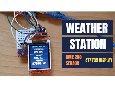
In this tutorial we are going to make a weather station project using a BME280 sensor and ST7735 Display.
Project info
Difficulty: Easy
Platforms: Arduino, SparkFun, Visuino
Estimated time: 1 hour
License: GNU General Public License, version 3 or later (GPL3+)
Items used in this project
Hardware components

Story
Step 1: What You Will Need
1 / 7
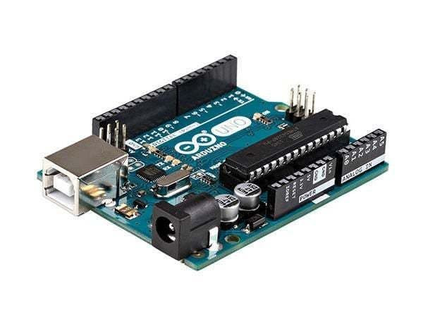
- Arduino UNO (Or any other Arduino)
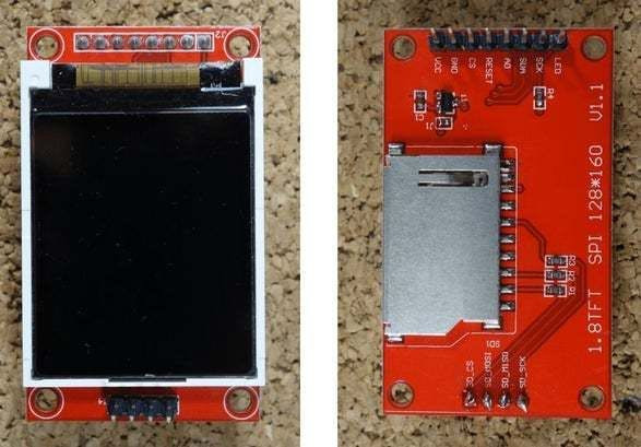
- LCD Display TFT 7735
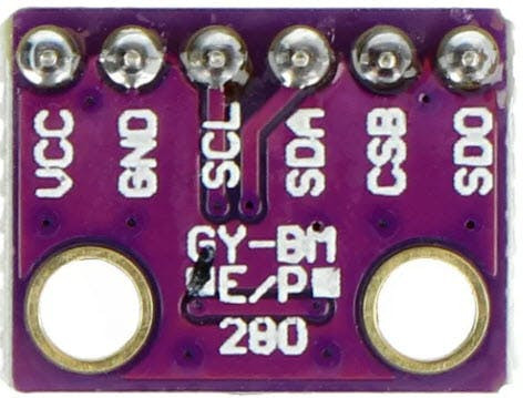
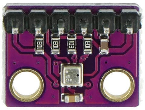
- BME280 Sensor
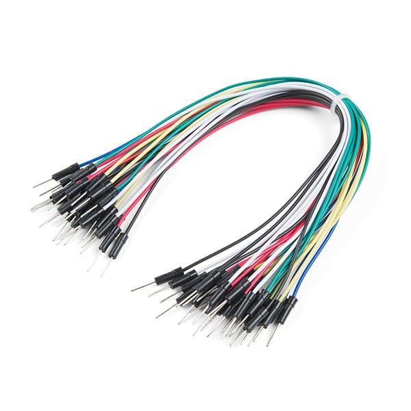
- Jumper wires
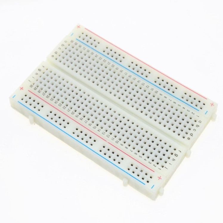
- Breadboard
- Visuino program: Download Visuino

Thank you PCBWay for supporting this tutorial and helping users learn more about electronics.
What I like about the PCBWay is that you can get 10 boards for approximately $5 which is really cost effective for professional made boards, not to mention how much time you save!
Go check them out here. They also offer a lot of other stuff in case you might need it like assembly, 3D printing, CNC machining and a lot more.
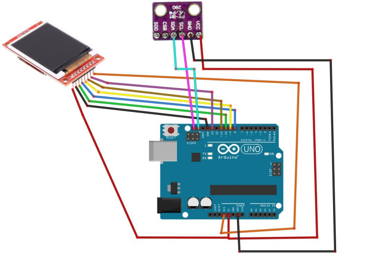
LCD TFT ST7735
Connect:
- 1.8 TFT Display PIN [LED] to Arduino PIN [3.3 V]
- 1.8 TFT Display PIN [SCK] to Arduino PIN [13]
- 1.8 TFT Display PIN [SDA] to Arduino PIN [11]
- 1.8 TFT Display PIN [A0 or DC] to Arduino PIN [9]
- 1.8 TFT Display PIN [RESET] to Arduino PIN [8]
- 1.8 TFT Display PIN [CS] to Arduino PIN [10]
- 1.8 TFT Display PIN [GND] to Arduino PIN [GND]
- 1.8 TFT Display PIN [VCC] to Arduino PIN [5V]
NOTE: Some Arduino boards have different SPI pins so make sure you check your board documentation.
BME280 Sensor
- Connect pin [VIN] to Arduino [V5]
- Connect pin [GND] to Arduino pin [GND]
- Connect pin [SDA] to Arduino pin [SDA]
- Connect pin [SCL] to Arduino pin [SCL]
1 / 2
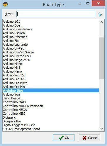
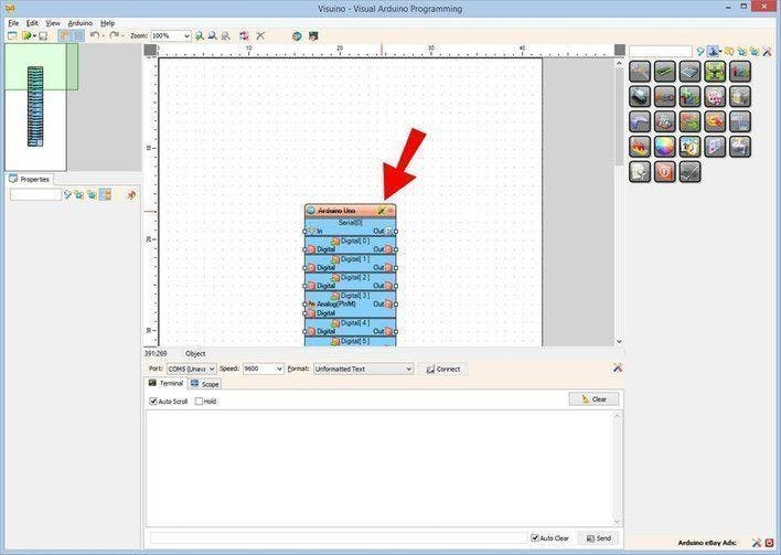
Start Visuino as shown in the first picture Click on the "Tools" button on the Arduino component (Picture 1) in Visuino When the dialog appears, select "Arduino UNO" as shown on Picture 2
Step 5: In Visuino Add Components1 / 2
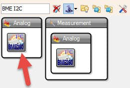
- Add "Pressure Temperature BME280 I2C" component
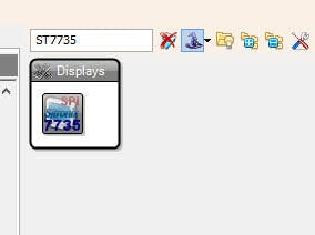
- Add "TFT Color Display ST7735" component
1 / 11
- Select "Display1" and set "Orientation" to goDown (this will change the directon of displaying)
Note: In case the display would not work try changing the Type under the properties window
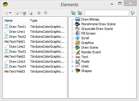
- Double click on the "Display1" and in the elements window expand "Text" and "Lines" on the right side and drag to the left side:
- 4X "Draw Text"
- 3X "Draw Line"
- 3X "Text Field"
- On the left side select:
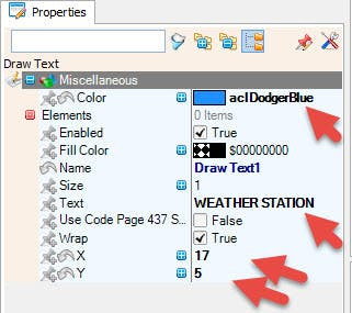
- - "Draw Text1" and in the properties window set "Size" to 1, "Color" to aclDodgerBlue and "X" to 17, "Y" to 5 and "Text" to WEATHER STATION
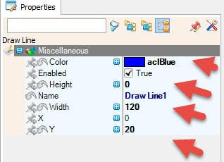
- - "Draw Line1" and in the properties window set "Height" to 0, "Width" to 120, "Color" to aclBlue and "Y" to 20
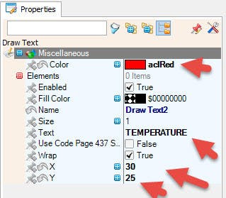
- - "Draw Text2" and in the properties window set "Size" to 1, "Color" to aclRed and "X" to 30 and "Y" to 25 and "Text" to TEMPERATURE
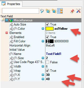
- - "Text Field1" and in the properties window set "Size" to 2, "Color" to aclYellow and "X" to 30 and "Y" to 40
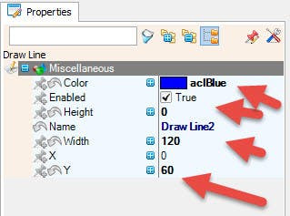
- - "Draw Line2" and in the properties window set "Height" to 0, "Width" to 120, "Color" to aclBlue and "Y" to 60
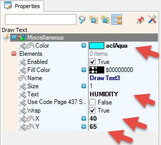
- - "Draw Text3" and in the properties window set "Size" to 1, "Color" to aclAqua and "X" to 40 and "Y" to 65 and "Text" to HUMIDITY
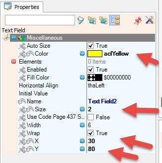
- - "Text Field2" and in the properties window set "Size" to 2, "Color" to aclYellow and "X" to 30 and "Y" to 80
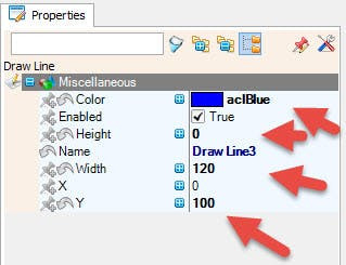
- - "Draw Line3" and in the properties window set "Height" to 0, "Width" to 120, "Color" to aclBlue and "Y" to 100
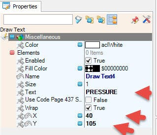
- - "Draw Text4" and in the properties window set "Size" to 1, "Color" to aclWhite and "X" to 40 and "Y" to 105 and "Text" to PRESSURE
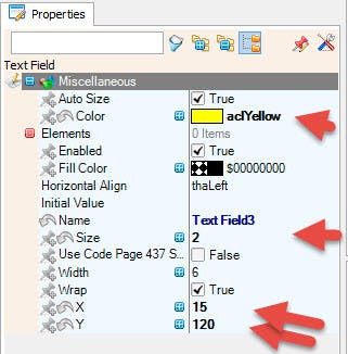
- - "Text Field3" and in the properties window set "Size" to 2, "Color" to aclYellow and "X" to 15 and "Y" to 120
1 / 2
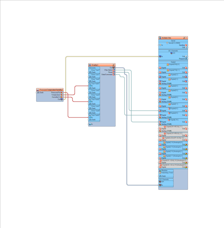
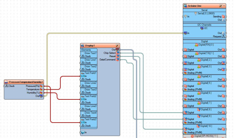
- Connect "PressureTemperatureHumidity1" pin I2C [Out] to Arduino I2C [In]
- Connect "PressureTemperatureHumidity1" pin [Pressure] to Display1>TextField3 [In]
- Connect "PressureTemperatureHumidity1" pin [Temperature] to Display1>TextField1 [In]
- Connect "PressureTemperatureHumidity1" pin [Humidity] to Display1>TextField2 [In]
- Connect "Display1" component pin [Out] to Arduino pin SPI [In]
- Connect "Display1" component pin [Chip Select] to Arduino Digital pin[10]
- Connect "Display1" component pin [Reset] to Arduino Digital pin[8]
- Connect "Display1" component pin [Register Select] to Arduino Digital pin[9]
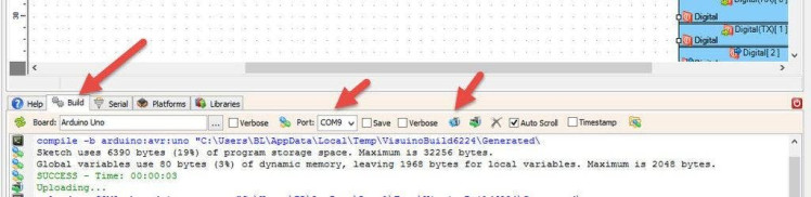
In Visuino, at the bottom click on the "Build" Tab, make sure the correct port is selected, then click on the "Compile/Build and Upload" button.
Step 9: PlayIf you power the Arduino UNO module, the LCD will start to show current values (TEMPERATURE, HUMIDITY, PRESSURE)
Congratulations! You have completed your project with Visuino. Also attached is the Visuino project, that I created for this Instructable, you can download it here and open it in Visuino: https://www.visuino.eu
Schematics, diagrams and documents
Code
Credits
Related products


Leave your feedback...