
Volume Indicator Neopixel Ws2812 Led Ring And Arduino

About the project
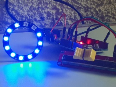
In this tutorial we will learn how to make a Volume Indicator using a Neopixel Ws2812 LED Ring and arduino. Watch the Video!
Project info
Difficulty: Moderate
Platforms: Adafruit, Arduino, Visuino
Estimated time: 1 hour
License: GNU Lesser General Public License version 3 or later (LGPL3+)
Items used in this project
Hardware components

Story
In this tutorial we will learn how to make a Volume Indicator using a Neopixel Ws2812 LED Ring and arduino.
Watch the Video!
Step 1: What You Will Need
1 / 4

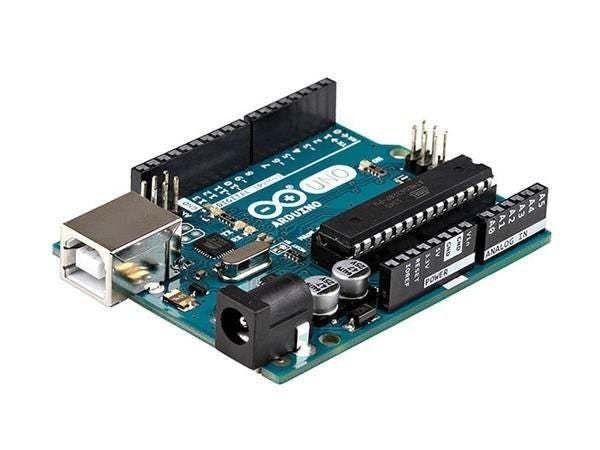
- Arduino Uno or any other Arduino board
- NeoPixel - RGB LED Ring
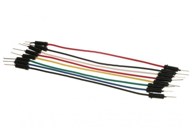
- Jumper wires
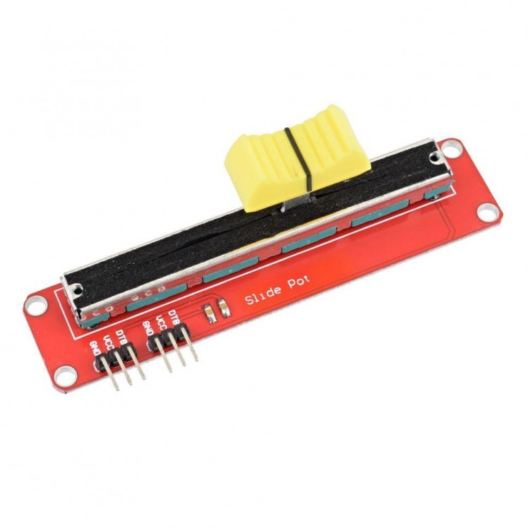
- Potentiometer
- Visuino software: Download here
Step 2: The Circuit
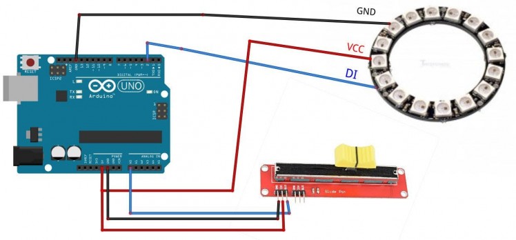
- Connect Arduino board pin 5V to LedRing pin VCC
- Connect Arduino board pin GND to LedRing pin GND
- Connect Arduino board Digital pin 2 to LedRing pin DI
- Connect potentiometer pin OTB to Arduino Analog Pin A0
- Connect potentiometer pin VCC to Arduino Analog Pin 5V
- Connect potentiometer pin GND to Arduino Pin GND
Step 3: Start Visuino, and Select the Arduino UNO Board Type
1 / 2
The Visuino: https://www.visuino.eu also needs to be installed. Download Free version or register for a Free Trial.
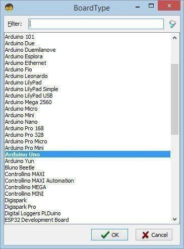
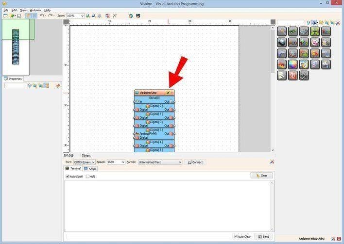
Start Visuino as shown in the first picture Click on the "Tools" button on the Arduino component (Picture 1) in Visuino When the dialog appears, select "Arduino UNO" as shown on Picture 2
Step 4: In Visuino Add Components
1 / 7
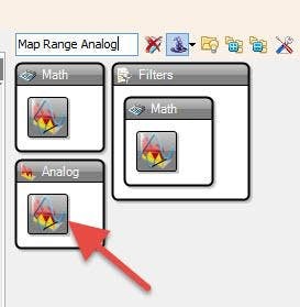
- Add "Map Range Analog" component
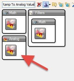
- Add "Ramp To Analog Value" component
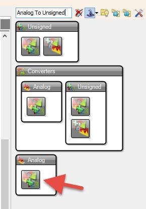
- Add "Analog To Unsigned" component
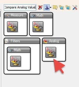
- Add 2X "Compare Analog Value" component
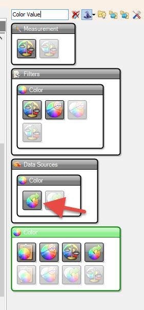
- Add 2X "Color Value" component
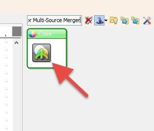
- Add "RGBW Color Multi-Source Merger" component
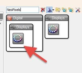
- Add "NeoPixels" component
Step 5: In Visuino Set Components
1 / 6
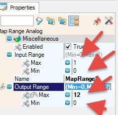
- Select "MapRange1" and in the properties set Input Range> Max to 1, and Input Range> Min to 0
- Select "MapRange1" and in the properties set Output Range> Max to 12, and Output Range> Min to 0
Note: Output Range> Max to 12 is the number of LED on the LEDRing
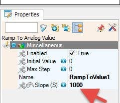
- Select "RampToValue1" and in the properties window set Slope (S) to 1000
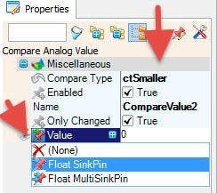
- Select "CompareValue1" and in the properties window set Compare Type to ctBigger and Value to 10also select Value field and click on the Pin Icon and select "Float Sink Pin"
- Select "CompareValue2" and in the properties window set Compare Type to ctSmaller also select Value field and click on the Pin Icon and select "Float Sink Pin"
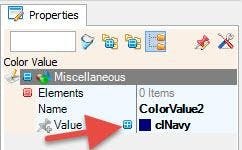
- Select "ColorValue2" and in the properties window set Value to clNavy
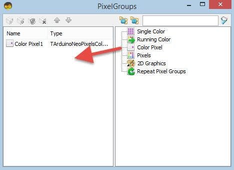
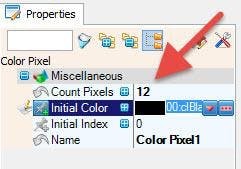
- Double click on the "NeoPixels1" and in the PixelGroups window drag ColorPixel to the left side, and in the properties window then set Count Pixels to 12
Note: Count Pixels 12 is the number of the LED on the LEDRing
Step 6: In Visuino Connect Components
1 / 2
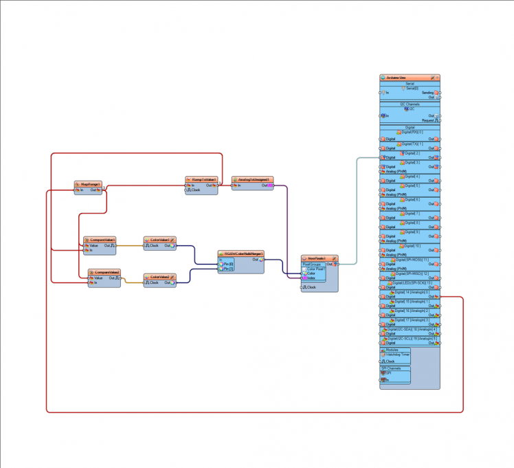
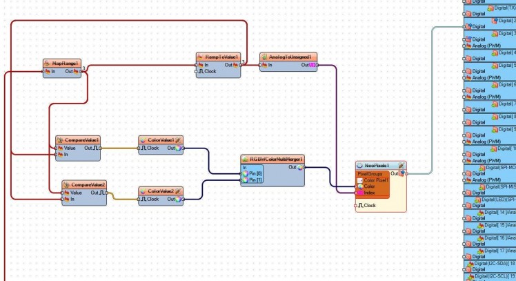
- Connect Arduino Analog pin [0] Out to MapRange1 pin In
- Connect "MapRange1" pin Out to RampToValue1 pin In, and CompareValue1 pin Value and CompareValue2 pin Value
- Connect "RampToValue1" pin Out to CompareValue1 pin In and CompareValue2 pin In and AnalogToUnsigned1 pin In
- Connect AnalogToUnsigned1 pin Out to NeoPixels1 pin Index
- Connect CompareValue1 pin Out to ColorValue1 pin Clock
- Connect CompareValue2 pin Out to ColorValue2 pin Clock
- Connect ColorValue1 pin Out to RGBWColorMultiMerger1 pin [0]
- Connect ColorValue2 pin Out to RGBWColorMultiMerger1 pin [1]
- Connect RGBWColorMultiMerger1 pin Out to NeoPixels1 pin Color
- Connect NeoPixels1 pin Out to Arduino Digital Pin 2
Step 7: Play
If you power the Arduino UNO module, and slide a potentiometer the LED Ring will indicate the Potentiometer position.You can use this approach in Audio Applications where you need to indicate the Volume position or any other project where some kind of visual indicator is needed.
Congratulations! You have completed your project with Visuino. Also attached is the Visuino project, that I created for this tutorial, you can download it and open it in Visuino: https://www.visuino.eu
Schematics, diagrams and documents
Code
Credits
Related products


Leave your feedback...