

Using An Ldr Sensor With Arduino

Made by tarantula3 / Artificial intelligence / Communication / Lights / Security / Sensors
About the project
In this tutorial i am going to show you how to use a LDR or Light Dependent resistor to turn on and off another circuit or a LED.
Project info
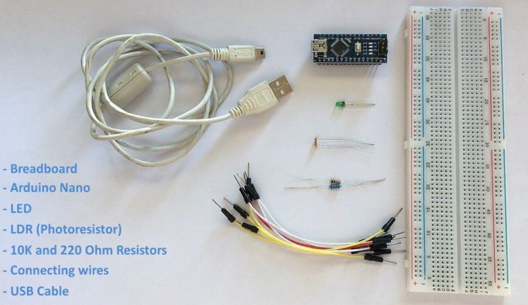
Items used in this project
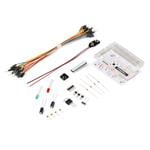
Hardware components


View all
Story
Video
Principle
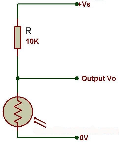
We are going to use a 10k resistor along with the LDR to create a voltage divider circuit. The varying resistance of the LDR is converted to a varying voltage that the analog pin of the Arduino will then be using in its logic.
The LDR is a special type of resistor which allows a lower voltage to pass through it (high resistance) whenever its dark and higher voltages to pass (low resistance) whenever there is a high intensity of light.
Harware Reqirement
Assembly
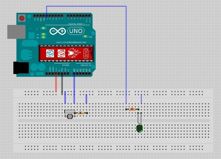
- and the shorter leg of the LED to the negative rail of the breadboard
- Connect the 3.3v output of the Arduino to the positive rail of the breadboard
- Connect the ground to the negative rail of the breadboard
- Place the LDR on the breadboard
- Attach the 10K resistor to one of the legs of the LDR
- Connect the A0 pin of the Arduino to the same column where the LDR and resistor is connected (Since the LDR gives out an analog voltage, it is connected to the analog input pin on the Arduino. The Arduino, with its built-in ADC (Analog to Digital Converter), then converts the analog voltage from 0-5V into a digital value in the range of 0-1023). - Now connect the other end of the 10K resistor to the negative rail - And the the second (free) leg of the LDR to the positive rail
Pretty much this is what we need for the light sensing. Basic circuits like this can be done without an Arduino aswell. However, if you want to log the values and use it to create charts, run other logics etc. I will recommend an Arduino or ESP8266 or may be a ESP32 for this.
Now, as we want our circuit to do something in the real world other than just displaying the values on the computer screen we will be attaching a LED to the circuit. The LED will turn on when its dark and will go off when its bright. To achieve this we will:
- Place the LED on the breadboard
- Connect the 220ohm resistor to the long leg (+ve) of the LED
- Then we will connect the other leg of the resistor to pin number 13 (digital pin) of the Arduino
The Code
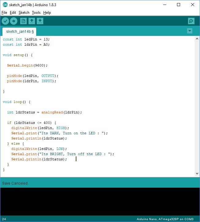
const int ledPin = 13;
const int ldrPin = A0;
void setup() {
Serial.begin(9600);
pinMode(ledPin, OUTPUT);
pinMode(ldrPin, INPUT);
}
void loop() {
int ldrStatus = analogRead(ldrPin);
if (ldrStatus <= 200) {
digitalWrite(ledPin, HIGH);
Serial.print("Its DARK, Turn on the LED : ");
Serial.println(ldrStatus);
} else {
digitalWrite(ledPin, LOW);
Serial.print("Its BRIGHT, Turn off the LED : ");
Serial.println(ldrStatus);
}
}
Video
Credits
Related products


Leave your feedback...