
Touchless Multifunctional Bedside Lamp With Digital Clock

Made by tarantula3 / Clocks / Displays / Home Automation / Lights / Sensors
About the project
I am going to make a touchless multipurpose bedside lamp, which will also include a digital clock, two power-ports and a USB charger
Project info
Difficulty: Easy
Platforms: Arduino, circuito.io, PCBWay
Estimated time: 5 hours
License: GNU General Public License, version 3 or later (GPL3+)
Items used in this project
Hardware components

Story
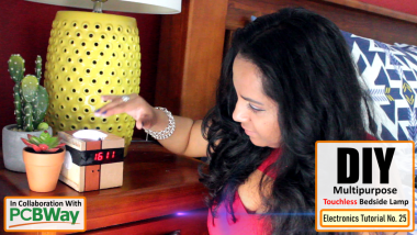
Whether you prefer to unwind the evening with a good book, play games on your phone, or wanna have some cozy time with your partner, the right bedside lighting can make a lot of difference.
In this project, I am going to make a touchless multipurpose bedside lamp, which will also include a digital clock, two power-ports and a USB charger.
This video tutorial is sponsored by PCBWay.
PCBway: only $5 for 10 pcbs from https://www.pcbway.com/?from=CZcouple
Woodworking
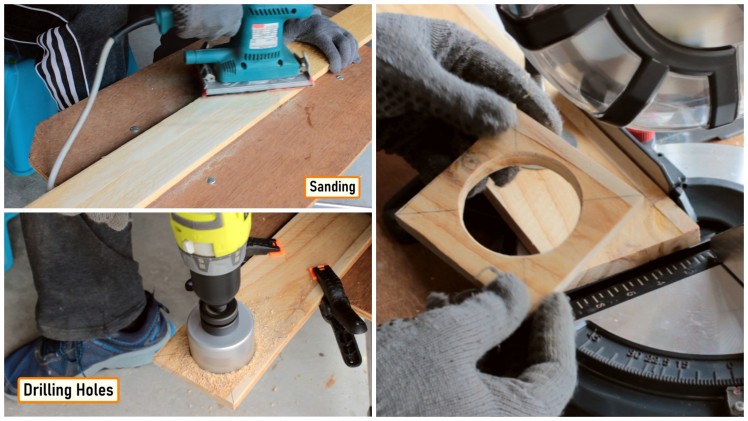
Lets start the project by sanding a pallet planks to give it a nice and smooth texture.Then, lets drill 3 holes for the top and the 2 sides of the night lamp.After drilling the holes lets extract the sides from the plank using a chop-saw or a hand-saw.
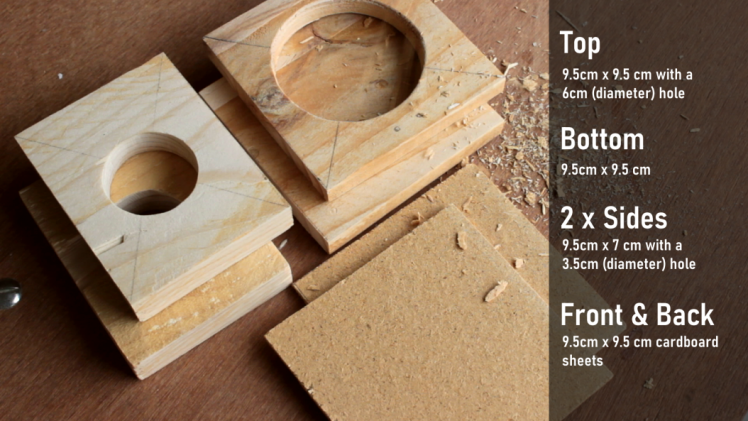
My pallet plank is 9.5cm wide and the lamp will be square in shape. So, rest of the measurements are based on that.
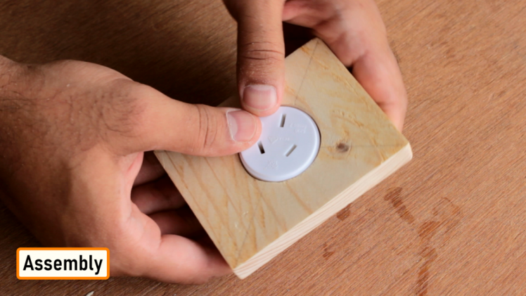
Once all the sides were ready its was time for me to join them all together.
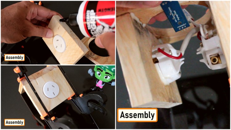
First of all I am getting the 2 x sides ready by gluing the power sockets into the holes.
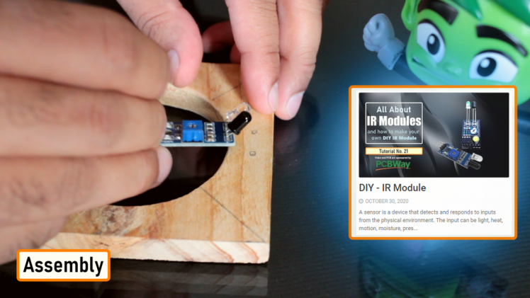
Next, I drilled 2x more holes for the IR sensor.
If you want to know more about IR sensors please check out my "Tutorial No 21 : DIY - IR Module : https://www.youtube.com/watch?v=_M8FQIPi1qk"
Next, one by one using wood glue I am joining the 2 x sides to the top of the lamp. At first I thought of using nails to join the sides, but soon I realized that by all means it was a very bad idea. Before gluing the 2nd side I connected the two power ports together using a copper wire.
Alright now, Lets look at the electronics bit.
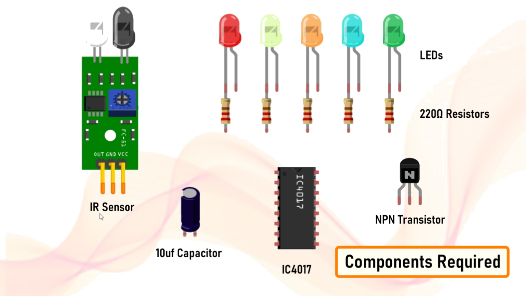
For the electronics bit we need:

4017 is a Decade Counter IC, it can count from 0 to 10. When a clock signal is received on Pin-14 the output turns to high one by one in a sequence.
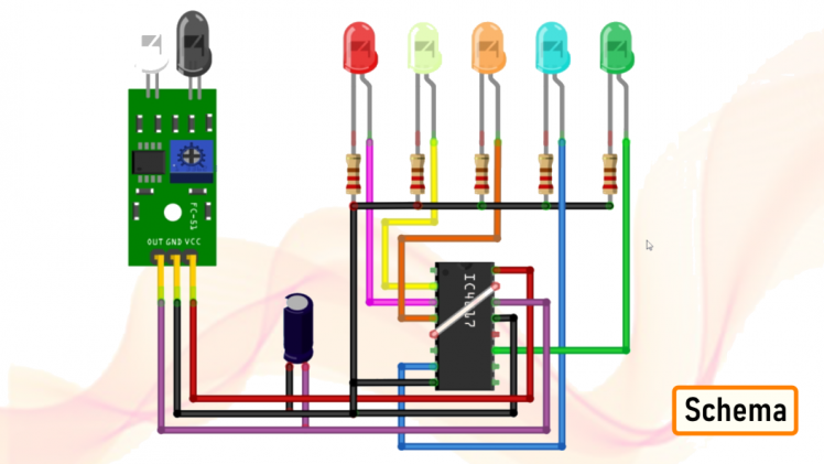
The signal from the IR-Sensor clocks the 4017 decade counter. Whenever a pulse is received at the clock input of IC, the counter increments the count and activates the corresponding output PIN. In our project we only need to count upto 5 so the 6th output from Pin-5 will be given to the Reset Pin-15. Sending a high signal to Pin-15 will reset the counter and it will skip counting the rest of the numbers and will start from the beginning. A capacitor is added to filter out too frequent detection of object by the IR sensor.
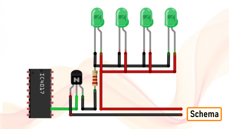
To add a cluster of LEDs to the circuit, we just need to feed the output from the IC to a transistor and the cluster can then be connect to the transistor. Similar to this setup.
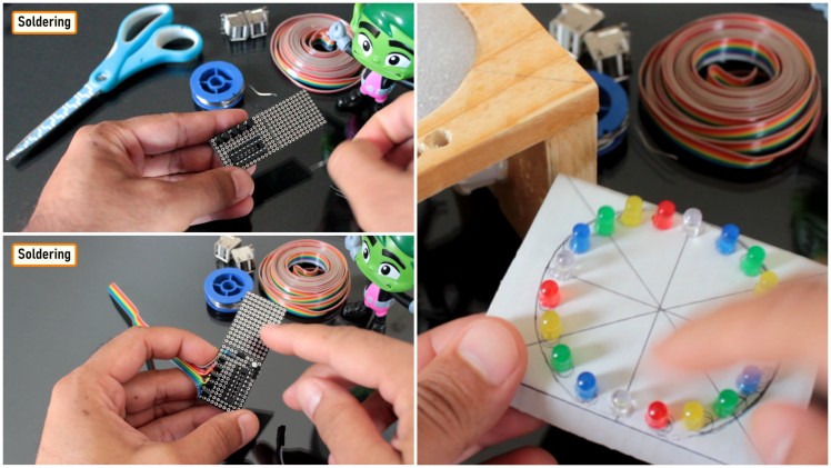
So, now lets start putting the components together. Lets solder the IC base followed by the 5 x NPN Transistors. Then, lets solder the 220Ω Resistors and the 10uf Capacitor to the board. I also added few pin headers to the board, 3 for the IR Sensor and 2 for the 5v power supply. The transistors are connected to the ribbon of wire which then connects to the cluster of LEDs that will slide under the top section.
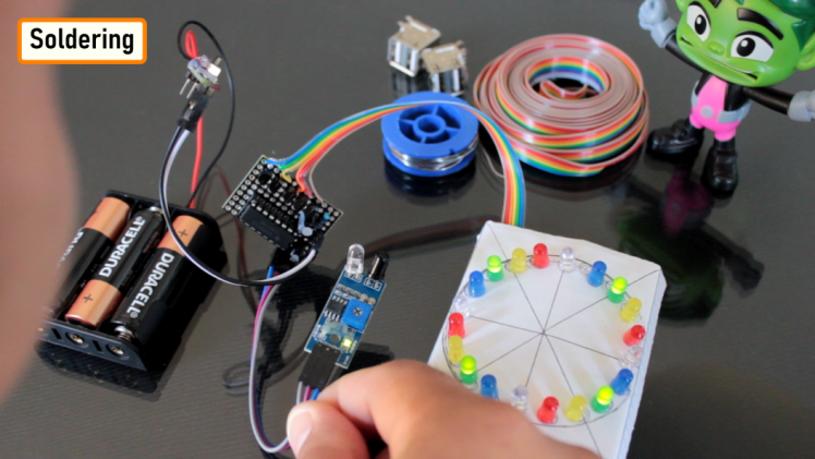
Before putting the circuit into production lets do a quick test. Bang, nailed it..
For the front bit I am using a 4-Bits DIY Electronic Digital Clock which I bought from AliExpress for just AU$2.40.
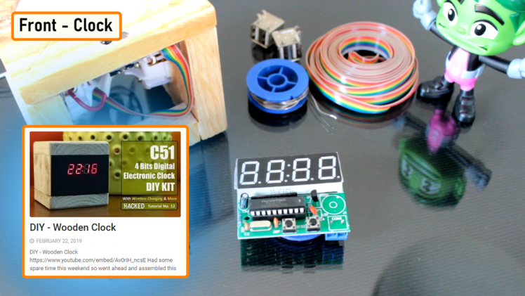
If you want to know more about this clock please checkout my "Tutorial No 12 : DIY - Wooden Clock : https://youtu.be/Av0riH_ncsE "
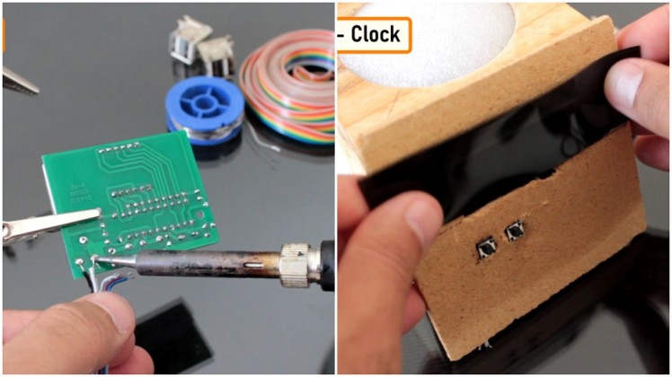
I moved the 2 push button switches from the board to the front panel of this lamp. My initial plan was to cover this entire setup with timber veneer sheet. However, I could not find one that was thin enough to not completely hide the 7-segment display. So, I ended up putting a black plastic film over the 7-segment display.
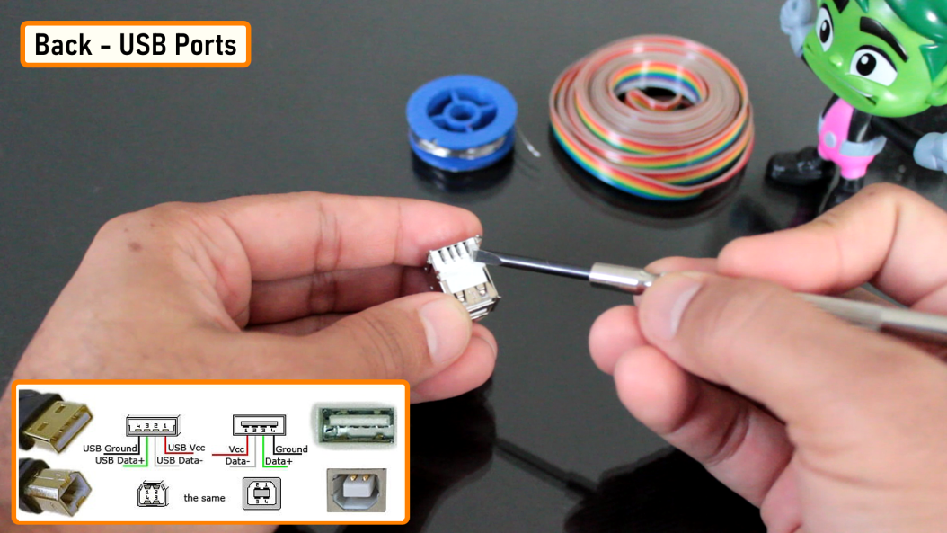
The back bit will host the USB ports and will also have a hole for the AC power chord.

Lets have a look at this USB port. When I am holding a USB port upside down the left most pin is the -ve pin and the rightmost is the +ve pin. The middle two are the data pins which I am not going to use in this project.
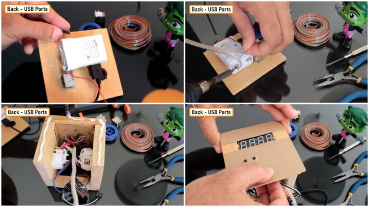
I used a Rubber Grommet to safeguard the power chord's hole.
To power the electronics bit I am using a USB charger. I glued the USB charger to the back bit of the lamp. I soldered the power supply cable to the USB charger and then hot-glued to protect it from touching the other electrical and electronic components.
Then I glued the back and the front plates of the lamp to the wooden frame. I soldered all the electronics components to the USB charger.

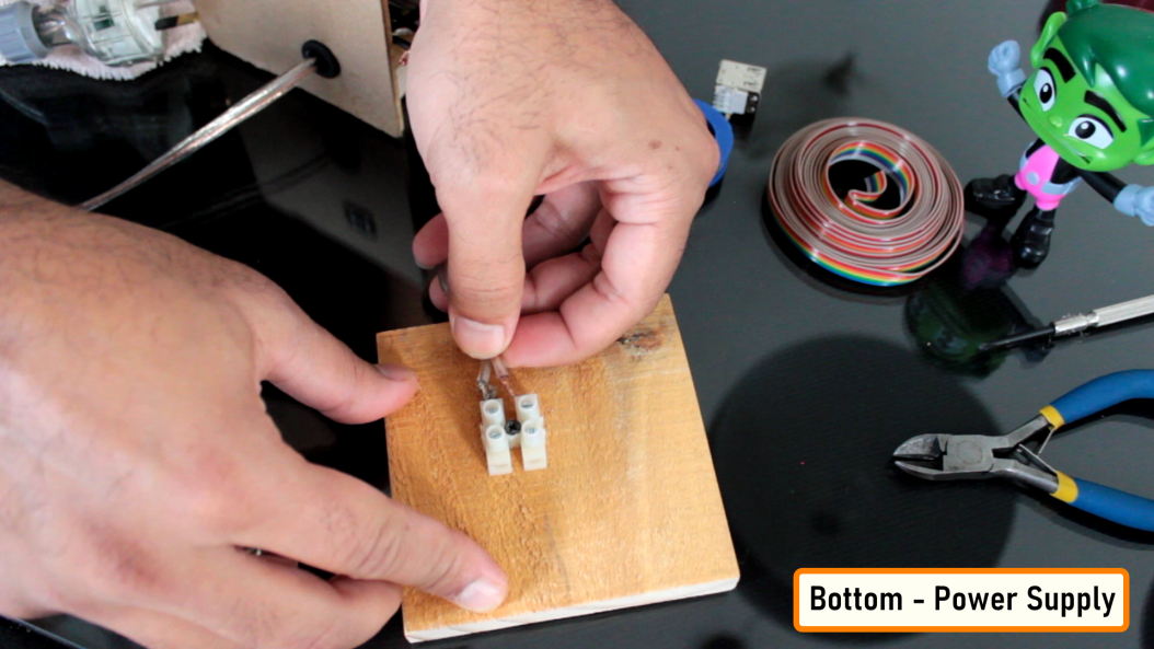
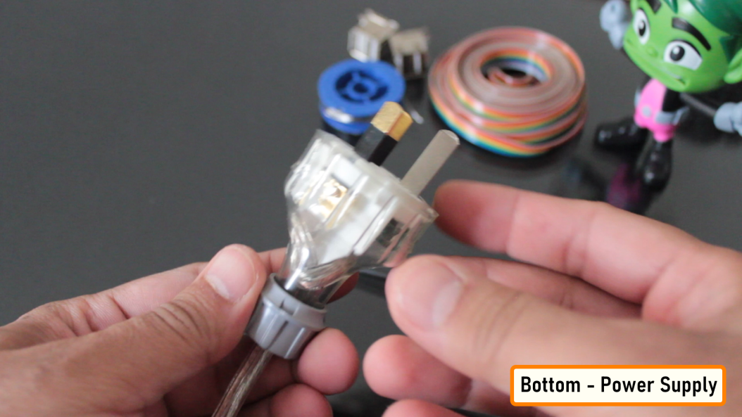
The bottom bit will hold the AC Power Cables. Since I don't want the AC cables to float around and cause short circuits inside the lamp, I screwed them to the base of the lamp.

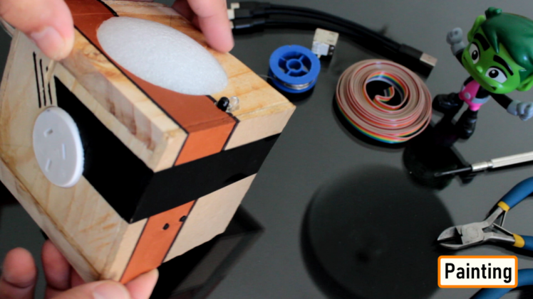
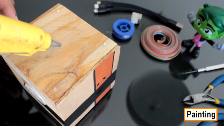
I painted the lamp a little bit to give it a modern look. Next, I superglued the black plastic film and painted its edges to match the whole setup.
To finalize the setup, I added a bit of hot-glue to the bottom of the lamp. These glue drops will stop this lamp from scratching my bedside table top.
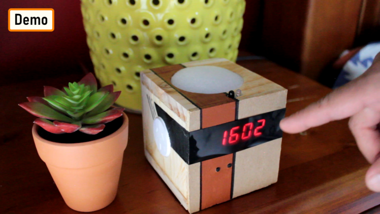
Demo
Covid has taught us many things, it has changed our life.
This project was an attempt to make things touchless. Hope you guys enjoyed it.
Thanks
Thanks again for checking my post. I hope it helps you.
If you want to support me subscribe to my YouTube Channel: https://www.youtube.com/user/tarantula3
Full Blog Post: https://diyfactory007.blogspot.com/2021/05/touchless-multifunctional-bedside-lamp.html
Video: https://youtu.be/r1r9jIgtcEk
Links:
Tutorial No 21 : DIY - IR Module :: https://www.youtube.com/watch?v=_M8FQIPi1qk
Tutorial No 12 : DIY - Wooden Clock :: https://youtu.be/Av0riH_ncsE
Support Me:
- BTC: 1M1PdxVxSTPLoMK91XnvEPksVuAa4J4dDp
- LTC: MQFkVkWimYngMwp5SMuSbMP4ADStjysstm
- DOGE: DDe7Fws24zf7acZevoT8uERnmisiHwR5st
- ETH: 0x939aa4e13ecb4b46663c8017986abc0d204cde60
- BAT: 0x939aa4e13ecb4b46663c8017986abc0d204cde60
- LBC: bZ8ANEJFsd2MNFfpoxBhtFNPboh7PmD7M2
Thanks, ca again in my next tutorial.
Credits
Related products


Leave your feedback...